- Select a language for the TTS:
- UK English Female
- UK English Male
- US English Female
- US English Male
- Australian Female
- Australian Male
- Language selected: (auto detect) - EN
Play all audios:
ABSTRACT Unlike hydrocarbon fuel, hydrogen is ‘green’ and attracting more and more attentions in energy and propulsion sectors due to the zero emission of CO and CO2. By applying numerical
simulations, we explore the physics of how a hydrogen-burnt flame can sustain pulsating combustion and its impact on the thermodynamic properties of a standing-wave combustor. We also
explain how implementing a heat exchanger can mitigate such pulsating combustion. The dynamic interactions of the unsteady flow-flame-acoustics-heater are examined by varying the mass flow
rate _ṁ_H2 and the heating bands’ surface temperature _T_H. The frequency and amplitude of the pulsating combustion are shown to depend strongly on _ṁ_H2. In addition, varying _T_H is shown
to lead to not only the molar fraction of the combustion species being changed but also the flame-sustained pulsating oscillations being mitigated somehow. Finally, nonlinearity is observed
and identified in the unsteady flow velocity and the two heat sources. SIMILAR CONTENT BEING VIEWED BY OTHERS PREVENTING A GLOBAL TRANSITION TO THERMOACOUSTIC INSTABILITY BY TARGETING LOCAL
DYNAMICS Article Open access 03 June 2022 CHOICE OF REACTION PROGRESS VARIABLE UNDER PREFERENTIAL DIFFUSION EFFECTS IN TURBULENT SYNGAS COMBUSTION BASED ON DETAILED CHEMISTRY DIRECT
NUMERICAL SIMULATIONS Article Open access 27 June 2024 ELECTRIC FIELDS IN A COUNTERFLOW NONPREMIXED FLAME: MEASUREMENT AND SIMULATION Article Open access 10 May 2023 INTRODUCTION Combustion
instability is an undesirable phenomenon that occurs frequently in lean premixed combustion systems for power generation or propulsion1,2,3. Typically, it results from dynamic interactions
between acoustics and premixed turbulent4 and laminar flames5. Combustion instability could be characterized by a loudly ‘singing’ and violently ‘dancing’ flame in longitudinal or azimuthal
direction (mode). Longitudinal-type instability has been intensively studied6. The dominant thermoacoustic instability is experimentally shown to switch by observing a shift from a low- to a
high-frequency ‘tone’. When combustion instability occurs7,8, it can cause severe vibration, overheating, flame flashback, and decreased performance9. In severe cases, the engines,
propellant systems and structures could be damaged. Intensive research has been conducted on hydrogen-involved combustion instability. Matsuyama et al.10 conducted LES (large eddy
simulations) on a single-element atmospheric combustor. It is found that the primary driving mechanism of 1k Hz combustion instability is the acoustically coupled pulsating motion of the
inner H2/O2 flame or periodic ignition of H2/O2 mixture. Recently, Hemchandra et al.11 discovered that there are two different mechanisms driving combustion instability. One is a strong
coupling between acoustics and hydrodynamic modes. The other one is a weak coupling resulting in semi-open-loop forcing of the flame by a self-sustained hydrodynamic mode. Urbano and Selle12
analyzed transverse combustion instabilities in a reduced-scale rocket motor. The interaction between acoustics and vorticity is found to be the main damping mechanism for coaxial H2/O2
flame-sustained instability. Injector-driven combustion instabilities are experimentally observed in a hydrogen/oxygen rocket motor13. The observed instabilities are a result of the
interaction between the injector resonant frequencies and the combustion chamber resonant frequencies. Combustion instability may be mitigated by applying two classical means. One is passive
control. Kim et al.14 experimentally evaluated the attenuation effect of sponge-like porous medium on combustion instability in a lab-scale swirl combustor. It is found that up to 40% of
pressure attenuation is achievable. A perforated plate/liner15 is analytically studied on damping combustion instability in an annular combustor16. Tao et al.16 show that a cooling/bias flow
can enhance the acoustic damping effect of such perforated plates/liners. The damping performance is found to be optimized at Strouhal number near 0.3. Similar stabilization effects are
observed on perforated slits on a modelled combustor17. Wu et al.18 actively tuned the acoustic damping of a Helmholtz resonator to mitigate combustion instability in a Y-shaped Rijke tube.
Approximately 60 dB sound pressure level (SPL) reduction is achieved by actively tuning the resonator’s back-wall. Similar implementation of a Helmholtz resonator19 is conducted on a Rijke
tube20. The other approach is active control using a developed controller. Phase-shift or PI (proportional-integral) controller is the typical one that is applied to suppress combustion
instabilities by using loudspeakers21,22. An excellent review on active control of combustion instability can be found in refs. 23,24. In addition to the classical active and passive control
approaches, alternative means have been proposed and tested. For example, Jocher et al.25 experimentally confirm that combustion instability could be controlled in open-loop configuration
by applying a magnetic field via reducing the growth rate of flame perturbations. Henderson and Xu26 experimentally study the effect of applying direct-current electric field on damping
thermoacoustic instability in a horizontal Rijke tube. Approximately 20 dB SPL reduction is achieved. Combustion instability is mitigated by actuating a swirler in a premixed methane-fuelled
combustor27. It is found that creating a higher-intensity turbulence and a swirl flow can alter the flame position and structure, and so the combustor stability behaviours. Fuel composition
is found to play an important role in generating and suppressing combustion instability. Diao et al.28 experimentally study the flame–acoustics interaction in a rectangular H2/O2
shear-coflow combustor with CH4 actively blended. It is found that heat release oscillations are significantly dampened, when gaseous methane is blended with gaseous hydrogen. The effect of
blending methane with hydrogen on combustion instability is experimentally studied29 on a swirl combustor. It is found that increasing hydrogen concentration (up to 30% in volume) in the
fuel leads to enhanced responses of the flame at non-resonant frequencies. Choi and Lee30 found that when hydrogen is added into syngas both acoustic pressure, unsteady heat release respond
sensitively and nonlinearly. Similar combustion instability studies of H2/CO/CH4 syngases were conducted on a partially premixed gas turbine combustor31. H2 contents are identified to play
an important role in producing higher-order (higher frequency) instability mode and mode-shifting. Acoustic measurements of a lean premixed combustor with hydrogen and methane or propane
fuelled confirm the key role of hydrogen in producing higher sound -pressure-level instability32. The effects of fuel composition on a premixed gas turbine combustion are well reviewed in
ref. 33, with emphasis being placed on combustion system stability34,35 and emissions. To the best knowledge of the authors, there are few reports in the literature discussing the physics
and mechanisms underlying hydrogen-fuelled pulsating combustion, and its impact on the thermodynamic properties of a standing-wave combustor. In addition, there is a lack of alternate but
effective means for preventing or mitigating combustion instability. In this work, an acoustically open−open premixed combustor fuelled with hydrogen–air mixture and a constant-temperature
heat exchanger is numerically studied to shed light on the dynamic flame−acoustics−heater interaction. The hydrogen mass flow rate \(\dot m_{{\mathrm{H}}_2}\) and the surface temperature
_T_H of the heating bands are evaluated. It is found that varying _T_H can lead to partial or complete change in the molar fraction of the combustion species and the mitigation in the
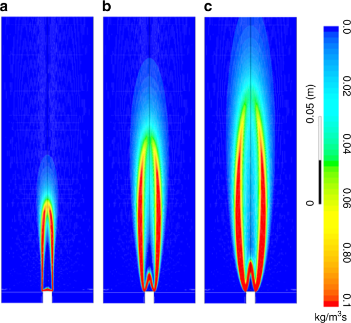
flame-sustained pulsating oscillations. Finally, nonlinearity is identified and observed on these heat sources. RESULTS EFFECT OF MASS FLOW RATE \(\DOT M_{{\MATHRM{H}}_2}\) As the mixture of
the hydrogen and air is burned, a conical shaped flame is confined in the combustor. Figure 1 shows the turbulent reaction rate as the hydrogen mass flow rate \(\dot m_{{\mathrm{H}}_2}\) is
set to three different values. It can be seen that the flame length and the surface area are dramatically increased, and so is the heat release. As it is well known that unsteady heat
release is an energy-efficient monopole-like sound source, acoustic pressure disturbances are generated with a small amplitude initially. However, whether the acoustic disturbances will grow
into limit cycle pulsating combustion oscillations needs to be examined. The effect of the flame on producing pulsating pressure oscillations is shown in Fig. 2. Figure 2a shows the time
evolution of the acoustic pressure fluctuations at the midpoint of the combustor in the axial direction, as the hydrogen mass flow rate \(\dot m_{{\mathrm{H}}_2}\) is set to 1.0 × 10⁻⁵ kg
s−1. It can be seen that there are small-amplitude pressure disturbances initially. However, such distances grow quickly into a limit cycle. Figure 2b shows the corresponding phase diagram
of the pressure fluctuations. The circle shape characterizes the limit cycle oscillations in phase plot. Figure 2c illustrates the phase diagram of the acoustic pressure, as the mass flow
rate \(\dot m_{{\mathrm{H}}_2}\) of the hydrogen is set to 5.0 × 10⁻⁶ kg s−1. It can be seen that a limit cycle is also produced. However, the amplitude is approximately 50% of that at
\(\dot m_{{\mathrm{H}}_2} = 1.0 \times 10^{ - 5}\,{\mathrm{{kg}}}\,{\mathrm{s}}^{ - 1}\). Further decreasing \(\dot m_{{\mathrm{H}}_2}\) leads to a reduction in the amplitude of the
pulsating oscillation, as shown in Fig. 2d. Unlike hydrocarbon fuels, hydrogen is a nonhydrocarbon that exhibits the largest mass diffusivity features. Figure 3 compares the profiles of the
reactants and combustion product species in both axial and radial directions, as the hydrogen mass flow rate \(\dot m_{{\mathrm{H}}_2}\) is set to three different values. The red colour
curves show the major hydrogen distribution. Along the axial direction (see Fig. 3a–c) the mole fraction begins to decay sharply; complete depletion of the hydrogen is achieved after the
reaction zone. In the radial direction, this finding is consistent with the variation of \(\dot m_{{\mathrm{H}}_2}\). The mole fraction profile of H2O is observed to vary dramatically in the
axial direction, as the hydrogen mass flow rate is changed (see the blue colour curves in Fig. 3a–c). As \(\dot m_{{\mathrm{H}}_2}\) is decreased from 1.0 × 10⁻⁵ to 1.0 × 10⁻⁶ kg s−1, the
separation between the preheat and reaction zones becomes more sharp. In other words, the wave/peak thickness, i.e. the maximum molar fraction region, is reduced. At _t_ = 2.0 s,
large-amplitude pulsating oscillations are produced by burning the mixture of H2 and O2 in the open−open tube. Such pulsating fluctuations propagate along the combustor and the fuel tube.
They in turn affect the local molar fractions of the species such as H2 and H2O. The profile of O2 is almost the same in the axial direction, as \(\dot m_{{\mathrm{H}}_2}\) is varied. It is
injected from the Bunsen burner, and so its mole fraction is increased gradually from the pre-reacting zone to the reacting zone and the after-reaction zone, and is finally ‘saturated’. As
far as the radial profiles (see Fig. 3d–f) are concerned, they are similar in shape for Fig. 3d, f, and in the growth rate for Fig. 3e. The shape profiles are similar especially near the
inner surface of the tube. The maximum mole fraction of H2 is reduced, and so is the thickness of the wave/peak of the water (H2O) profile. The hydrogen mole fraction begins to decrease from
the point _r/R_ = 0 and it becomes much sharper, as \(\dot m_{{\mathrm{H}}_2}\) is reduced to \(\dot m_{{\mathrm{H}}_2} = 1.0 \times 10^{ - 6}\,{\mathrm{{kg}}}\,{\mathrm{s}}^{ - 1}\). In
general, H2, O2 and H2O are all a function of the spatial distance through the flame. Both water and hydrogen exist in the preheat zone. Note that more complicated 21-step chemical reactions
are studied, as discussed in Supplementary Note 1. The new results with the 21 chemical reaction mechanisms/steps are provided in Supplementary Table 1. Comparison is made between the
multiple-step and the much-simplified one-step reaction in terms of the temperature and velocity contours, and the combustion-driven pressure and the heat of reaction pulsating oscillations.
Interested readers can find more details in Supplementary Figs. 1 and 2, and insightful discussion in Supplementary Note 1. As the mixture of the hydrogen and air is burned, the
instantaneous temperature at the midpoint of the combustor in the axial direction is monitored in real time. This is shown in Fig. 4 with \(\dot m_{{\mathrm{H}}_2}\) being set to three
different values. It can be seen from Fig. 4a–c that the temperature is decreased dramatically, as \(\dot m_{{\mathrm{H}}_2}\) is decreased. The temperature fluctuates dramatically before
the limit cycle oscillations are produced by the flame, i.e. _t_ ≤ 0.5 s. However, with limit cycles being completely generated at _t_ ≥ 1.0 s, the temperature seems to be ‘saturated’. To
gain insight into the fluctuations of the temperature, a phase diagram of the instantaneous temperature _T_(_t_) is plotted, as shown in Fig. 4d–f. It can be clearly seen that the gradient
of the temperature, i.e. d_T_/d_t_, is non-zero. This means that the temperature is periodically oscillating around its mean value. Furthermore, the oscillation amplitude is dramatically
reduced with a decrease in \(\dot m_{{\mathrm{H}}_2}\) (Fig. 4d–f). Finally, the fluctuating trend of the temperature reveals that the heat-to-acoustics energy conversion is nonirreversible.
The mode shapes of the acoustic pressure fluctuations are determined, and are discussed in Supplementary Note 2 (shown in Supplementary Fig. 3). Comparison is then made with the case of
using CH4 as the fuel. It is shown that the maximum pressure amplitude is observed near the mid-point of the combustor in the axial direction. A pressure node is expected at the combustor
outlet, no matter whether CH4 or H2 is fuelled. EFFECT OF THE HEATING BANDS Heating bands with a constant surface temperature are implemented, aiming to dampen and/or prevent the onset of
the flame-sustained pulsating oscillations. Time evolution of the pressure fluctuations as the temperature of the heating bands is increased from 300 to 1300 K at _t_ = 2.0 s is shown in
Fig. 5a, as \(\dot m_{{\mathrm{H}}_2}\)is set to three different values. It can be seen that as the hydrogen mass flow rate is greater than \(\dot m_{{\mathrm{H}}_2} = 5.0 \times 10^{ -
6}\,{\mathrm{{kg}}}\,{\mathrm{s}}^{ - 1}\), increasing the temperature of the heating bands leads to a mitigation in the limit cycle oscillations. However, when the hydrogen mass flow rate
is reduced to \(\dot m_{{\mathrm{H}}_2} = 1.0 \times 10^{ - 6}\,{\mathrm{{kg}}}\,{\mathrm{s}}^{ - 1}\), actuating the heating bands is found to successfully prevent the onset of the limit
cycle oscillations, as denoted by the solid green colour cure in Fig. 5a. To quantify the damping effect of the heating bands, the instantaneous acoustical energy _E_a(t) per unit volume of
the combustor is determined: $$E_{\mathrm{a}}(t) = \frac{{\frac{\omega }{{2\pi }}\mathop {\smallint }\nolimits_t^{t + 2\pi /\omega } \left[ {p\prime (t)} \right]^2{\mathrm{d}}t}}{{2\gamma
p_0}},$$ (1) where _p′_(_t_) is the acoustic pressure fluctuation, _ω_ is the oscillation frequency, _γ_ = 1.4 is the specific heat ratio, and _p_0 = 1.01325 × 10⁵ Pa is the mean pressure.
Note that the total acoustical energy \(E_{\mathrm{a}}^{{\mathrm{{tot}}}}\) at a given time can be determined by integrating _E_a(_t_) over the entire combustor volume. If a 3D cylindrical
coordinate is considered, then \(E_{\mathrm{a}}^{{\mathrm{{tot}}}}(t) = \mathop {\smallint }\nolimits_0^{2\pi } {\mathrm{d}}\vartheta \,\mathop {\smallint }\nolimits_0^R
r{\mathrm{d}}r\,\mathop {\smallint }\nolimits_0^L E_{\mathrm{a}}(t)\,{\mathrm{d}}x\). Since the combustor volume is specified with the constant cross-sectional area and the axial length L,
_E_a can be applied to characterize the intensity of combustion oscillations. Time evolution of the acoustical energy _E_a is shown in Fig. 5b as \(\dot m_{{\mathrm{H}}_2}\) is set to three
different values. It can be seen that as \(\dot m_{{\mathrm{H}}_2} = 1.0 \times 10^{ - 5}\,{\mathrm{{kg}}}\,{\mathrm{s}}^{ - 1}\), the acoustical energy _E_a is reduced by 61.7% from _t_ =
2.0 s to _t_ = 4.0 s. Approximately 81% acoustical energy reduction is achieved at \(\dot m_{{\mathrm{H}}_2} = 5.0 \times 10^{ - 6}\,{\mathrm{{kg}}}\,{\mathrm{s}}^{ - 1}\). At \(\dot
m_{{\mathrm{H}}_2} = 1.0 \times 10^{ - 6}\,{\mathrm{{kg}}}\,{\mathrm{s}}^{ - 1}\), the pressure fluctuations are successfully prevented from growing into limit cycles, as observed for \(\dot
m_{{\mathrm{H}}_2} = 5.0 \times 10^{ - 6}\,{\mathrm{{kg}}}\,{\mathrm{s}}^{ - 1}\) and \(\dot m_{{\mathrm{H}}_2} = 1.0 \times 10^{ - 5}\,{\mathrm{{kg}}}\,{\mathrm{s}}^{ - 1}\). This confirms
that the heating bands are applicable to dampen flame-sustained pulsating oscillations. Time-frequency analysis is conducted to study the heat of reaction of the hydrogen-fuelled flame and
the total heat fluxes of the heating bands before and after changing the temperature of the heating bands (Fig. 6). It can be seen that the nonlinearity is associated with the heat release
rates of the flame and the heating bands, due to the comparable frequency peaks. Before the heating bands’ temperature is changed, i.e. _t_ ≤ 2 s, the heat release of the flame is associated
with multiple modes at different frequencies. The dominant mode frequency is approximately 204 Hz (see Fig. 5a). However, the harmonic modes are excited as the heating bands’ temperature is
increased to 1300 K at 2.0 < _t_ ≤ 4.0 s. Nonlinearity characteristics of the combustion system are further identified by conducting the frequency spectrum analysis of the flow velocity.
This is shown in Fig. 7, as the hydrogen mass flow rate \(\dot m_{{\mathrm{H}}_2}\) is set to three different values. Figure 7a–c shows the time evolution of the instantaneous velocity. It
can be seen that as \(\dot m_{{\mathrm{H}}_2}\)is decreased, with no change in the temperature of the heating bands (_t_ ≤ 2.0 s), the mean velocity is reduced from 3.1 to 1.53 m s−1. The
amplitude of the velocity fluctuation is also decreased dramatically. Figure 7d–f illustrates the frequency spectrum of the velocity fluctuation, before and after the temperature of the
heating bands is changed. It can be seen that ~4% of the dominant frequency shift occurs from _t_ ≤ 2.0 to _t_ > 2.0 s. A similar frequency shift is observed from 203.0 to 177.6 Hz, as
the mass flow rate \(\dot m_{{\mathrm{H}}_2}\) is decreased from 1.0 × 10⁻⁵ to 1.0 × 10⁻⁶ kg s−1. However, the dominant frequency shift is approximately 12.7%. This is most likely due to the
fact that the H2 mass flow rate and the total heat release are reduced. The mean temperature and the speed of sound in the combustor are also decreased. To maintain the standing-wave mode
shape and to satisfy the inlet and outlet boundary conditions, the dominant frequency of the H2-excited oscillations is thus decreased. In general, the flame-excited pulsating oscillation
signature is found to depend strongly on the hydrogen mass flow rate. The effect of the heating bands on combustion species is also examined, as shown in Fig. 3. Comparison is made before
and after the surface temperature _T_H of the heating bands is increased from 300 to 1300 K at _t_ = 2.0 s. It can be seen from Fig. 3a–c that the mole fraction profiles of the reactants of
H2 and O2, and the product H2O at _T_H = 1300 K are quite similar to those at _T_H = 300 K in the axial direction. Furthermore, the thickness of ‘the wave/peak’ profile is also the same.
This is most likely due to the negligible effect of the mean heat release of the heating bands on the hydrogen-fuelled flame, as they are placed far away downstream of the combustor. As
shown in Fig. 3d–f, the radial profiles of the mole fraction of O2 look quite similar, before and after _T_H is changed. This is most likely due to the fact that the inner burner is
associated with a mixture of hydrogen and air. In addition, there is a simultaneous flow of air injected from the bottom of the cylindrical tube (see Fig. 8). The mole fraction profiles of
H2 and H2O, especially the maximum molar fraction of the species at _r/R_ = 0, are however different. This may be due to the fact that the periodic combustion oscillations are dampened with
the actuation of the heating bands, which affects the hydrogen and H2O distribution along the radial direction. The oscillation intensity and frequency may contribute to the radial profiles
variation of H2 and H2O. As revealed by Rayleigh1,2, limit cycle pulsating combustion occurs due to the unsteady heat release, and acoustic pressure fluctuations are in phase. In order to
shed light on the dynamic flame−flow−heater interaction, Rayleigh index angle _θ_RI is determined (Supplementary Note 3) to check whether the unsteady heat release from the flame \(Q\prime
_{\mathrm{f}}\) and the heating bands \(Q\prime _{\mathrm{H}}\) are in or out of phase with the acoustic pressure fluctuations. _θ_RI is defined as the phase difference between the heat
release and the pressure fluctuation at the frequency _ω_ at any instant. Supplementary Figures 4 and 5 show the time evolution of the phase difference between the acoustic disturbances and
the unsteady heat release from the flame and the heater, respectively. DISCUSSION We have numerically shown how hydrogen-fuelled flame can sustain self-excited pulsating oscillations, and
its impact on the thermodynamic properties of a standing-wave combustor with heating bands confined. The physics behind the flame−acoustics−heater−flow interaction is numerically examined.
It is found that the hydrogen mass flow rate \(\dot m_{{\mathrm{H}}_2}\) determines not only the pulsating combustion characteristics but also the molar fraction profiles of the combustion
species. Approximately 13% of the dominant frequency shift is observed in the dominant mode. Furthermore, the combustor is found to be highly nonlinear in terms of the acoustic velocity and
heat of reaction _Q_f from the flame and the heat flux _Q_H from the heating bands. Finally, varying the surface temperature _T_H of the heating bands is shown to be able to successfully
prevent the onset of limit cycle pulsating oscillations excited by the hydrogen-fuelled flame. By conducting further analyses on the mode shape and by determining the Rayleigh index angle it
has been confirmed that, when limit cycle pulsating combustion occurs, the combustor is a standing-wave one. Rayleigh index angle reveals that the unsteady heat release constructively
interacts with the acoustic disturbances in the flame, while destructive interactions are observed on the heating bands. This is consistent with the Rayleigh criterion and explains why the
heating bands can be applied to dampen pulsating combustion oscillations. In addition, it is interesting to show that increasing the surface temperature of the heating bands leads to the
combustion species profiles being varied. The present work sheds light on the fundamental physics and mechanism underlying hydrogen-fuelled combustion instability. It also opens up an
alternative control means to dampen or to prevent the onset of the pulsating oscillations. METHODS MODEL SET-UP The geometry of the open−open standing-wave combustor is schematically shown
in Fig. 8a. Hydrogen and air are injected into the combustor. The inner burner is associated with a mixture of the hydrogen and air. However, there is a simultaneous flow of air injected
from the bottom of the cylindrical tube. Six heating bands (of length 30 mm) with the constant surface temperature are equally spaced in the radial direction. They are placed at a distance
of _L_h away from the top open end of the combustor. Note that these heating bands represent a classical heater consisting of distributed heating elements. We chose six heating bands here.
Although the choice could have been three or four. A larger number of heating bands with a smaller surface area helps to keep the total heat release rate unchanged to achieve the effective
control performance. Near the bottom open end is a Bunsen burner with an inner diameter of 5.0 mm. The height of the Bunsen burner is _L_b. The overall view of the 2D mesh generated by using
Ansys ICEM CFD is shown in Fig. 8b. The mesh consists of 25,868 quadrilateral elements, 372 elements along the axis of the tube and 76 elements along the radius. Near the heating bands and
the Bunsen burner, a finer grid is applied, as shown in Fig. 8b. The mesh is chosen on the basis of our mesh-independence study as discussed in Supplementary Note 4. The mesh-independence
results are provided in Supplementary Figs. 6 and 7. Note that a 2D combustor is modelled for simplicity and for reducing the computational time and cost. However, a 3D modelled combustor is
also investigated and compared with the 2D one for completeness, as discussed in Supplementary Note 5. This is shown in Supplementary Fig. 8. Approximately 16% difference is found between
the pressure pulsation amplitudes predicted from the 2D and 3D combustors. However, the computational time is increased by 400%. With the flame confined, there is an unsteady heat release
and a mean flow results from the convection effect. In addition, unsteady heat release is an energy-efficient monopole-like acoustics source36,37. Acoustic distances are produced and
propagated along the combustor. The interaction between the acoustic disturbances and the heating bands leads to further unsteady heat release. When the temperature of the mean flow is
higher than the surface temperature of the heating bands, they absorb the heat released from the flame. Otherwise, heat is produced by the heating bands and transferred to the mean flow. The
heat transfer process in our modelled combustor is unsteady. Thus, the current modelled combustor involves the dynamic interaction between the premixed flame, the unsteady flow, the
acoustics and the heating bands. GOVERNING EQUATIONS The flame−acoustics−flow−heater interaction problem38,39 is modelled by solving certain equations governing fluid dynamics and the
chemical combustion reaction. All these equations need to be solved simultaneously and some of them are coupled, e.g. the fluid velocity will determine how the combustion species40 will
spread through the computational domain and at which particular locations in the numerical domain there might be more or less chemical reaction taking place. The governing equations of mass,
momentum, species fraction, energy conservations in the combustor are given as $$\frac{{\partial \rho }}{{\partial t}} + \frac{{\partial (\rho {\mathbf{u}}_i)}}{{\partial x_i}} = 0,$$ (2)
$$\frac{{\partial (\rho {\mathbf{u}}_i)}}{{\partial t}} + \frac{{\partial (\rho {\mathbf{u}}_i{\mathbf{u}}_j)}}{{\partial x_i}} = - \frac{{\partial p}}{{\partial t}} + \frac{\partial
}{{\partial x_i}}\left[ {\mu _{\mathrm{t}}\left( {\frac{{\partial {\mathbf{u}}_i}}{{\partial x_j}} + \frac{{\partial {\mathbf{u}}_j}}{{\partial x_i}}} \right)} \right. - \left.
{\frac{2}{3}\mu _{\mathrm{t}}\frac{{\partial {\mathbf{u}}_k}}{{\partial x_k}}} \right]\delta _{ij} + \rho g\delta _{i3},$$ (3) $$\frac{{\partial (\rho \chi _k)}}{{\partial t}} +
\frac{{\partial (\rho u_i\chi _k)}}{{\partial x_i}} = \frac{{\partial J_k}}{{\partial t}} + R_k,$$ (4) $${\frac{\partial (\rho E)}{\partial t} + \frac{\partial \left[ u_{i} (\rho E + p)
\right]}{\partial x_{i}} = \frac{\partial}{\partial x_{j}}\left( k_{\mathrm{eff}} \frac{\partial {\mathrm{T}}}{\partial x_{j}} - \mathop {\sum }\limits_{j} h_{j} J_{j} + {\mathbf{u}}_{i}
\left[ \mu_{\mathrm{eff}} \left( \frac{\partial {\mathbf{u}}_{j}}{\partial x_{i}} + \frac{\partial {\mathbf{u}}_{i}}{\partial x_{j}} \right) - \frac{2}{3} \mu _{\mathrm{eff}} \frac{\partial
{\mathbf{u}}_{k}}{\partial x_{k}} \delta_{ij} \right] \right),}$$ (5) where _χ__k_ is the local mass fraction of the _k_th species, _J__k_ is the diffusion flux of the _k_th species, _R__k_
is the net rate of the _k_th species by chemical reaction, _δ__ij_ denotes the Kronecker delta function and _δ__ij_ = 1 when _i_ = _j_; otherwise _δ__ij_ = 0. The turbulent viscosity _μ_t is
introduced to model the effect of turbulence on the flow according to the Boussinesq hypothesis. This unknown needs to be determined via an additional modelling, for which the RNG _k_−ε
model in ANSYS Fluent is employed. The turbulent viscosity is computed from _k_, the turbulent kinetic energy, and _ε_, the turbulent dissipation, as given in the following expression: $$\mu
_{\mathrm{t}} = {\mathrm{0}}{\mathrm{.0845}}\rho \frac{{k^2}}{\varepsilon }.$$ (6) The turbulent kinetic energy _k_ and the dissipation rate _ε_ are determined from the transport equations
of similar structures to the governing equations for the fluid flow. They are given as $$\frac{{\partial (\rho k)}}{{\partial t}} + \frac{{\partial (\rho k{\mathbf{u}}_i)}}{{\partial x_i}} =
\frac{\partial }{{\partial x_j}}\left( {\alpha _k\mu _{{\mathrm{eff}}}\frac{{\partial k}}{{\partial x_j}}} \right) + G_{\mathrm{k}} + G_{\mathrm{b}} - \rho \varepsilon - Y_M$$ (7) and
$$\frac{{\partial (\rho \varepsilon )}}{{\partial t}} + \frac{{\partial (\rho \varepsilon {\mathbf{u}}_i)}}{{\partial x_i}} = \frac{\partial }{{\partial x_j}}\left( {\alpha _\varepsilon \mu
_{{\mathrm{eff}}}\frac{{\partial \varepsilon }}{{\partial x_j}}} \right) + C_{1\varepsilon }\frac{\varepsilon }{k}\left( {G_{\mathrm{k}} + C_{3\varepsilon }G_{\mathrm{b}}} \right) -
C_{2\varepsilon }\rho \frac{{\varepsilon ^2}}{k} - R_\varepsilon,$$ (8) where _G_k and _G_b denote the production of turbulence kinetic energy resulting from the mean velocity gradient and
buoyancy effects, respectively. _Y__M_ describes part of the overall dissipation rate due to the fluctuation dilatation in compressible turbulence. The eddy-dissipation _k–ε_ model is used
to determine the production term _R__k_ in Eq. (4). This production term is computed with the following expression: $$R_k = \min \left( {4.0\nu {\prime}_k{\mathrm{MW}}_k\rho
\frac{\varepsilon }{k}{\mathrm{min}}_i\left( {\frac{{\chi _i}}{{\nu {\prime}_iM_i}}} \right),2.0\nu {\prime}_k{\mathrm{MW}}_k\rho \frac{\varepsilon }{k}\frac{{\mathop {\sum }\nolimits_i \chi
_i}}{{\mathop {\sum }\nolimits_j^N v{\prime{\!}\prime}_j{\mathrm{MW}}_j}}} \right),$$ (9) where MW_k_ is the molecular weight of the species _k_, \(v{\prime}_k\) denotes the stoichiometric
coefficient for the reactant _k_th species and \(v{\prime{\!}\prime}_j\) is the stoichiometric coefficient for the product _j_th species in the chemical reaction. Further details can be
found in ref. 41 or the Fluent documentation, which contains more information about the modelling of the governing equations. A more complex turbulence model42, e.g. RSM (Reynolds stress
model), could have been applied. For comparison, RSM (involving seven equations) is also implemented and evaluated as described in Supplementary Note 6 (Supplementary Figs. 9 and 10). It is
shown that the hydrogen-driven pulsating combustion43 is successfully generated by using either the RSM or the _k_–_ε_ model. To reduce the computational time and cost, we chose the _k_–_ε_
turbulence model in the current studies. MODEL SETTINGS The essential properties of the computational fluid dynamics (CFD) model are set as follows: (1) a pressure-based coupled solver; (2)
unsteady simulations with a time step of Δ_t_ = 1.0 × 10⁻⁴ s and a second-order discretization; (3) a spatial discretization: second-order pressure discretization, and third-order MUSCL
scheme for all equations, except the turbulence dissipation (second-order upwind); (4) hydrogen–air mixture (air components: nitrogen (76.8%), oxygen (23.2%) in mass); (5) species transport
model, volumetric reactions, eddy-dissipation turbulence–chemistry interaction; (6) a turbulence model: _k−ε_−RNG; and (7) the gravitational acceleration _g_ = −9.81 m s−2 along the centre
line of the open tube. Boundary conditions arethe following: (a) tube walls are adiabatic; (b) the Bunsen burner wall is adiabatic; (c) heating bands/elements: prescribed constant
temperature (setting _T_ = 300 K for 0.0 ≤ _t_ ≤ 2.0, _T_ = 1300 K for 2.2 s < _t_, controlled via UDF (user-defined function); (d) the Bunsen burner tip is a mass flow inlet; (e) the
bottom end of the open tube is a pressure inlet (i.e. 0 Pa); (f) the top end of the open tube is a pressure outlet (i.e. 0 Pa). The numerical simulation is started with a flow field as the
initial solution, which includes a steady flame, i.e. a flame that is developed in a steady-state simulation. The fuel–air ratio40 is set to 1.0 for all current simulations. Detailed
information is summarized in Supplementary Table 2. DATA POST-PROCESSING Short-time Fourier Transform (STFT) is used to analyse the data regarding the acoustic pressure, velocity, and the
reaction of heat and heat fluxes. STFT is developed based on the DFT (Discrete Fourier Transform). Let us consider Z(_n_) as an _N_-point acquired pressure signal in the time domain _t_(_N_)
= _N_Δ_t_, and let _W__N_ = exp(−_j_2_π_/_N_) and \(j = \sqrt { - 1}\). The DFT of z(_n_) is Z(_n_) = DFT{Z(_n_)} is defined as $${\mathbf{Z}}(n) \equiv \mathop {\sum }\limits_{k = 0}^{N -
1} {\mathbf{z}}(n)W_N^{nk}, \quad 0 \le i < N $$ (10) Frequency-domain figures are obtained with Δ_t_ = 1/10,000 s and _N_ = 8192 and a Hamming window. DATA AVAILABILITY The data that
support the findings of this research are available from the corresponding author on request. CODE AVAILABILITY The code (case files) and data sets generated by using ANSYS FLUENT 15.1
during this study are available from the corresponding author on request. REFERENCES * Rayleigh, L. The explanation of certain acoustical phenomena. _Nature_ 18, 319–321 (1878). Article ADS
Google Scholar * Bragg, S. L. Noise and oscillations in jet engines. _Nature_ 201, 123–129 (1964). Article ADS Google Scholar * Raun, R. L., Beckstead, M. W., Finlinson, J. C. &
Brooks, K. P. A review of Rijke tubes Rijke burners and related devices. _Prog. Energy Combust. Sci._ 19, 313–364 (1993). Article Google Scholar * Hajialigol, N. & Mazaheri, K. Thermal
response of a turbulent premixed flame to the imposed inlet oscillating velocity. _Energy_ 118, 209–220 (2017). Article Google Scholar * Zhang, Z., Guan, D., Zheng, Y. & Li, G.
Characterizing premixed laminar flame–acoustics nonlinear interaction. _Energy Convers. Manag._ 98, 331–339 (2015). Article Google Scholar * Zhao, H. et al. Experimental study of
equivalence ratio and fuel flow rate effects on nonlinear thermoacoustic instability in a swirl combustor. _Appl. Energy_ 208, 123–131 (2017). Article ADS Google Scholar * Li, J. &
Morgans, A. S. Simplified models for the thermodynamic properties along a combustor and their effect on thermoacoustic instability prediction. _Fuel_ 184, 735–748 (2016). Article Google
Scholar * Laera, D., Campa, G. & Camporeale, S. M. A finite element method for a weakly nonlinear dynamic analysis and bifurcation tracking of thermo-acoustic instability in
longitudinal and annular combustors. _Appl. Energy_ 187, 216–227 (2017). Article Google Scholar * Bauerheim, M. et al. Transmission and reflection of acoustic and entropy waves through a
stator–rotor stage. _J. Sound Vib._ 374, 260–278 (2016). Article ADS Google Scholar * Matsuyama, S. et al. Large-Eddy simulation of high-frequency combustion instability in a
single-element atmospheric combustor. _J. Propul. Pow._ 32(), 628–645 (2016). Article Google Scholar * Hemchandra, S., Shanbhogue, S., Hong, S. & Ghoneim, A. F. Role of hydrodynamic
shear layer stability in driving combustion instability in a premixed propane-air backward-facing step combustor. _Phys. Rev. Fluids_ 3, 063201 (2018). Article ADS Google Scholar *
Urbano, A. & Selle, L. Driving and damping mechanisms for transverse combustion instabilities in liquid rocket engines. _J. Fluid Mech._ 820, R2 (2017).
https://doi.org/10.1017/jfm.2017.227. Article ADS MathSciNet Google Scholar * Groning, S., Hardi, J. S., Suslov, D. & Oschwald, M. Injector-driven combustion instabilities in a
hydrogen/oxygen rocket combustor. _J. Propul. Power_ 32, 560–573 (2016). Article Google Scholar * Kim, Y. J., Lee, D. K. & Kim, Y. Experimental study on combustion instability and
attenuation characteristics in the lab-scale gas turbine combustor with a sponge-like porous medium. _J. Mech. Sci. Technol._ 32, 1879–1887 (2018). Article Google Scholar * Wu, G., Li, S.,
Zhao, H., Yang, X. L. & Jiaqiang, E. Experimental and frequency-domain study of acoustic damping of single-layer perforated plates. _Aerosp. Sci. Technol._ 69, 432–438 (2017). Article
Google Scholar * Tao, W., Zhang, M. & Li, L. Modeling of acoustic damping of perforations on the combustion instability of annular aero-engine combustors. In _ASME Turbo Expo:
Turbomachinery Technical Conference and Exposition_, GT2017–64282, https://doi.org/10.1115/GT2017-64282 (2017). * Surendran, A. & Heckl, M. A. Passive instability control by a heat
exchanger in a combustor with non-uniform temperature. _Int. J. Spray. Combust._ 9, 380–393 (2017). Article Google Scholar * Wu, G., Lu, Z. L., Pan, W. C., Guan, Y. H. & Ji, C. Z.
Numerical and experimental demonstration of actively passive mitigating self-sustained thermoacoustic oscillations. _Appl. Energy_ 222, 257–266 (2018). Article Google Scholar * Zalluhoglu,
U. & Olgac, N. A study of Helmholtz resonators to stabilize thermoacoustically driven pressure oscillations. _J. Acoust. Soc. Am._ 139, 1962–1973 (2016). Article ADS Google Scholar *
Zhang, G. Y., Wang, X. Y., Li, L., Jing, X. D. & Sun, X. F. Control of thermoacoustic instability with a drum-like silencer. _J. Sound Vib._ 406, 253–276 (2017). Article ADS Google
Scholar * Zalluhoglu, U., Kammer, A. S. & Olgac, N. Delayed feedback control laws for Rijke tube thermoacoustic instability, synthesis, and experimental validation. _IEEE T. Contr.
Syst. T._ 24, 1861–1868 (2016). Article Google Scholar * Li, S. et al. Theoretical and experimental demonstration of minimizing self-excited thermoacoustic oscillations by applying
anti-sound technique. _Appl. Energy_ 181, 399–407 (2016). Article Google Scholar * Dowling, A. P. & Morgans, A. S. Feedback control of combustion oscillations. _Annu. Rev. Fluid Mech._
37, 151–182 (2005). Article ADS MathSciNet Google Scholar * Li, S. et al. Theoretical and experimental demonstration of minimizing self-excited thermoacoustic oscillations by applying
anti-sound technique. _Appl. Energy_ 181, 399–407 (2016). Article Google Scholar * Jocher, A., Pitsch, H., Gomez, T., Bonnety, J. & Legros, G. Combustion instability mitigation by
magnetic fields. _Phys. Rev. E_ 95, 063113 (2017). Article ADS Google Scholar * Henderson, B. R. & Xu, K. N. G. Electric field damping of Rijke tube combustion instabilities. _J.
Propul. Power_ 34, 85–96 (2018). Article Google Scholar * Gopakumar, R., Mondal, S., Paul, R., Mahesh, S. & Chaudhuri, S. Mitigating instability by actuating the swirler in a
combustor. _Combust. Flame_ 165, 361–363 (2016). Article Google Scholar * Diao, Q., Ghosh, A. & Yu, K. H. Combustion instability suppression in gaseous oxygen/hydrogen combustors using
methane dilution. _J. Propul. Power_ 33, 719–729 (2017). Article Google Scholar * Yilmaz, I., Ratner, A., Ilbas, M. & Huang, Y. Experimental investigation of thermoacoustic coupling
using blended hydrogen-methane fuels in a low swirl burner. _Int. J. Hydrog. Energ._ 35, 329–336 (2010). Article Google Scholar * Choi, O. & Lee, M. C. Investigation into the
combustion instability of synthetic natural gases using high speed flame images and their proper orthogonal decomposition. _Int. J. Hydrog. Energ._ 41, 20731–20743 (2016). Article Google
Scholar * Park, J. & Lee, M. C. Combustion instability characteristics of H2/CO/CH4 syngases and synthetic natural gases in a partially-premixed gas turbine combustor: Part I—Frequency
and mode analysis. _Int. J. Hydrog. Energ._ 41, 7484–7493 (2016). Article Google Scholar * Wicksall, D. & Agrawal, A. Acoustics measurements in a lean premixed combustor operated on
hydrogen/hydrocarbon fuel mixtures. _Int. J. Hydrog. Energ._ 32, 1103–1112 (2007). Article Google Scholar * Taamallah, S. et al. Fuel flexibility, stability and emissions in premixed
hydrogen-rich gas turbine combustion: technology, fundamentals, and numerical simulations. _Appl. Energy_ 154, 1020–1047 (2015). Article Google Scholar * Qian, C., Bing, W., Huiqiang, Z.,
Yunlong, Z. & Wei, G. Numerical investigation of H2/air combustion instability driven by large scale vortex in supersonic mixing layers. _Int. J. Hydrog. Energ._ 41, 3171–3184 (2016).
Article Google Scholar * Hoferichter, V. & Sattelmayer, T. Boundary layer flashback in premixed hydrogen-air flames with acoustic excitation. _J. Eng. Gas Turb. Power_ 140, 051502
(2018). Article Google Scholar * Wang, G. Q., Li, Y. Y., Li, L. & Qi, F. Experimental and theoretical investigation on cellular instability of methanol/air flames. _Fuel_ 225, 95–103
(2018). Article Google Scholar * Lee, K., Kim, H., Park, P., Yang, S. & Ko, Y. CO2 radiation heat loss effects on NOx emissions and combustion instabilities in lean premixed flames.
_Fuel_ 106, 682–689 (2013). Article Google Scholar * Li, J. X., Xia, Y., Morgans, A. S. & Han, X. S. Numerical prediction of combustion instability limit cycle oscillations for a
combustor with a long flame. _Combust. Flame_ 185, 28–43 (2017). Article Google Scholar * Cintra, B. F. C. & Fernandes, E. C. Thermoacoustic instabilities of lean disc flames. _Fuel_
184, 973–986 (2016). Article Google Scholar * Pires, J. M. & Fernandes, E. C. Combined effect of equivalence ratio and velocity gradients on flame stability and emission formation.
_Fuel_ 222, 800–809 (2018). Article Google Scholar * Versteeg, H. K. & Malalasekera, W. _An Introduction to Computational Fluid Dynamics: The Finite Volume Method_ (Pearson Education,
London, UK, 2007). * Zhao, D., Gutmark, E. & de Goey, P. A review of cavity-based trapped vortex, ultra-compact, high-g, inter-turbine combustors. _Progress. Energy Combust. Sci._ 66,
42–82 (2018). Article Google Scholar * Backhaus, S. & Swift, G. W. A thermoacoustic Stirling heat engine. _Nature_ 399, 335–338 (1999). Article ADS Google Scholar Download
references ACKNOWLEDGEMENTS We gratefully acknowledge the financial support provided by the University of Canterbury, New Zealand (grant no. 452STUPDZ) and National Research Foundation
Singapore (grant no. NRF2016NRF-NSFC001-102). AUTHOR INFORMATION AUTHORS AND AFFILIATIONS * Department of Mechanical Engineering, College of Engineering, University of Canterbury, Private
Bag 4800, Christchurch, 8140, New Zealand Dan Zhao * School of Energy and Power Engineering, Jiangsu University of Science and Technology, Mengxi Rd 2, 212003, Zhenjiang City, Jiangsu
Province, China Yiheng Guan * College of Engineering, Nanyang Technological University, 50 Nanyang Avenue, Singapore, 639798, Singapore Arne Reinecke Authors * Dan Zhao View author
publications You can also search for this author inPubMed Google Scholar * Yiheng Guan View author publications You can also search for this author inPubMed Google Scholar * Arne Reinecke
View author publications You can also search for this author inPubMed Google Scholar CONTRIBUTIONS D.Z. and A.R. conducted the numerical computation. D.Z. and Y.G. analysed and discussed the
results. D.Z. conceived and initialized the project, and wrote the paper along with Y.G. CORRESPONDING AUTHOR Correspondence to Dan Zhao. ETHICS DECLARATIONS COMPETING INTERESTS The authors
declare no competing interests. ADDITIONAL INFORMATION PUBLISHER’S NOTE: Springer Nature remains neutral with regard to jurisdictional claims in published maps and institutional
affiliations. SUPPLEMENTARY INFORMATION SUPPLEMENTARY INFORMATION RIGHTS AND PERMISSIONS OPEN ACCESS This article is licensed under a Creative Commons Attribution 4.0 International License,
which permits use, sharing, adaptation, distribution and reproduction in any medium or format, as long as you give appropriate credit to the original author(s) and the source, provide a link
to the Creative Commons license, and indicate if changes were made. The images or other third party material in this article are included in the article’s Creative Commons license, unless
indicated otherwise in a credit line to the material. If material is not included in the article’s Creative Commons license and your intended use is not permitted by statutory regulation or
exceeds the permitted use, you will need to obtain permission directly from the copyright holder. To view a copy of this license, visit http://creativecommons.org/licenses/by/4.0/. Reprints
and permissions ABOUT THIS ARTICLE CITE THIS ARTICLE Zhao, D., Guan, Y. & Reinecke, A. Characterizing hydrogen-fuelled pulsating combustion on thermodynamic properties of a combustor.
_Commun Phys_ 2, 44 (2019). https://doi.org/10.1038/s42005-019-0142-8 Download citation * Received: 09 August 2018 * Accepted: 11 March 2019 * Published: 06 May 2019 * DOI:
https://doi.org/10.1038/s42005-019-0142-8 SHARE THIS ARTICLE Anyone you share the following link with will be able to read this content: Get shareable link Sorry, a shareable link is not
currently available for this article. Copy to clipboard Provided by the Springer Nature SharedIt content-sharing initiative