- Select a language for the TTS:
- UK English Female
- UK English Male
- US English Female
- US English Male
- Australian Female
- Australian Male
- Language selected: (auto detect) - EN
Play all audios:
ABSTRACT We demonstrate a sandwich configuration for microfluidic manipulation in LiNbO3 platform based on photovoltaic effect and the behaviours of dielectric microdroplet under this
sandwich configuration are investigated. It is found that the microdroplet can generate in the form of liquid bridge inside the LiNbO3-based sandwich structure under the governing
dielectrophoretic force and the dynamic process of microdroplet generation highly depends on the substrate combinations. Dynamic features found for different combinations are explained by
the different electrostatic field distribution basing on the finite-element simulation results. Moreover, the electrostatic field required by the microdroplet generation is estimated through
meniscus evolution and it is found in good agreement with the simulated electrostatic field inside the sandwich gap. Several kinds of microdroplet manipulations are attempted in this work.
We suggest that the local dielectrophoretic force acting on the microdroplet depends on the distribution of the accumulated irradiation dosage. Without using any additional pumping or
jetting actuator, the microdroplet can be step-moved, deformed or patterned by the inconsecutive dot-irradiation scheme, as well as elastically stretched out and back or smoothly guided in a
designed pass by the consecutive line-irradiation scheme. SIMILAR CONTENT BEING VIEWED BY OTHERS DIRECT ELECTRIFICATION OF SILICON MICROFLUIDICS FOR ELECTRIC FIELD APPLICATIONS Article Open
access 19 June 2023 OPTOFLUIDIC TRANSPORT AND ASSEMBLY OF NANOPARTICLES USING AN ALL-DIELECTRIC QUASI-BIC METASURFACE Article Open access 28 July 2023 LIGHT-DRIVEN PERISTALTIC PUMPING BY AN
ACTUATING SPLAY-BEND STRIP Article Open access 04 April 2023 INTRODUCTION Lithium niobate (LN) is regarded as a potential substrate material for integrated optics industry due to its strong
electro-optical, pyroelectric, piezoelectric and nonlinear optical properties. As LN shows good biocompatibility, many biomedical functions based on photonics are expected to be integrated
on LN chips. In such a way, lab-on-chips may open new horizons on biological analysis1,2,3,4,5, clinical diagnostics6,7,8 and drug discovery9,10,11. For example, T. Yang and P. Minzioni _et
al_. proposed a novel optofluidic design for real-time sorting based on the cell mechanical properties. The sorting component can be realized on LN substrates with many other functional
units (e.g. waveguide and SAW actuator) integrated for cell counting and alignment1,2,3. Among various integrated functions, the most important one required by the LN-based lab-on-chip is
the manipulation of microdroplets, which is the key technique for reducing both reactant consumption and reaction time. In the past few years, a couple of droplet-based microfluidic systems
have been proposed basing on photovoltaic effect12,13,14,15,16,17,18,19,20,21,22,23. A. C. Muir _et al_.12 first reported the change of inherent wetting property of LN crystal surface under
UV irradiation. Their results clearly show that photo-excited carriers might be used for arranging microdroplets. Later, M. Esseling and C. Denz _et al_. made a throughout investigation on
dielectrophoretic (DEP) trapping in two-dimensional patterns on LiNbO3:Fe (LN:Fe) crystals13,14,15,16,17. While M. Carrascosa _et al_. studied the DEP trapping both in experimental and
theoretical aspects and they established numerical algorithm to predict the trapped object distribution18,19,20,21,22,23. Recently, an optofluidic droplet router based on photorefractive
effect has been subtly fabricated by Esseling _et al_., who used DEP force created by the bulk photovoltaic effect to route and steer microdroplets on LN substrate, realizing the
microfluidic manipulation in a LN-based lab-on-chip17 for the first time. The DEP force originates from the unequal electrostatic force of polarization charges induced on dielectrics when
they are subjected to nonuniform electric fields24 and it has been widely used for the manipulation of microfluidics and micron-sized particles such as biological droplets and cells25,26.
Thomas _et al_. presented a novel particle-trapping design by using negative DEP to trap cells in high conductivity physiological media25. Kumar _et al_. showed many kinds of opto-electric
manipulations in microfluidics that utilized DEP force in their review26. For most of the above designs, electrodes have to be fabricated on the substrates25,26,27,28, which certainly
increases the complexity of the devices. For photovoltaic materials such as LN:Fe crystals, DEP force can be created directly in the substrate through photovoltaic current29 (without using
electrodes), which enables more flexible and advantageous devices fabricated possibly. The previous microdroplet manipulation usually employed one LN substrate. For example, in Esseling’s
wrok17 channel structure was made of PDMS and LN was used as the bottom of the channels. Through the photovoltaic effect of the LN substrate the incident illumination pattern was transformed
into electric field distributions. Droplet, actuated by the pumping component, moved inside channel structure and this electric field distribution was responsible for the droplet
manipulations. However, with the development of lab-on-chip, more complicated configuration is very likely to be required. In this paper, we demonstrate a sandwich configuration based on LN
substrates. The sandwich structure allows the microdroplets to be generated in the form of liquid bridge and move in the gap of two LN substrates under the combined actions of the two
substrates. The microdroplets sandwiched between two LN substrates will be affected by the electrostatic forces generated on both substrates simultaneously. In this case, the manipulation
force could be enhanced by the proper configuration of double substrates and consequently the droplet can be manipulated actively in multimode with higher efficiency. Thus, pumping or
jetting component can be removed from the microfluidic system, which is often required by an isolated design. As the microdroplet behaviours under the combined actions of the two substrates
haven’t been reported yet until now, the study regarding this issue is useful not only to the novel design of future LN-based lab-on-chip but also to the understanding of the kinetic
mechanism of electrified liquid on the LN substrate. EXPERIMENTAL PROCEDURES The sandwich substrates used in our experiment consist of two c-cut congruent LN:Fe crystals (doped with 0.03 wt%
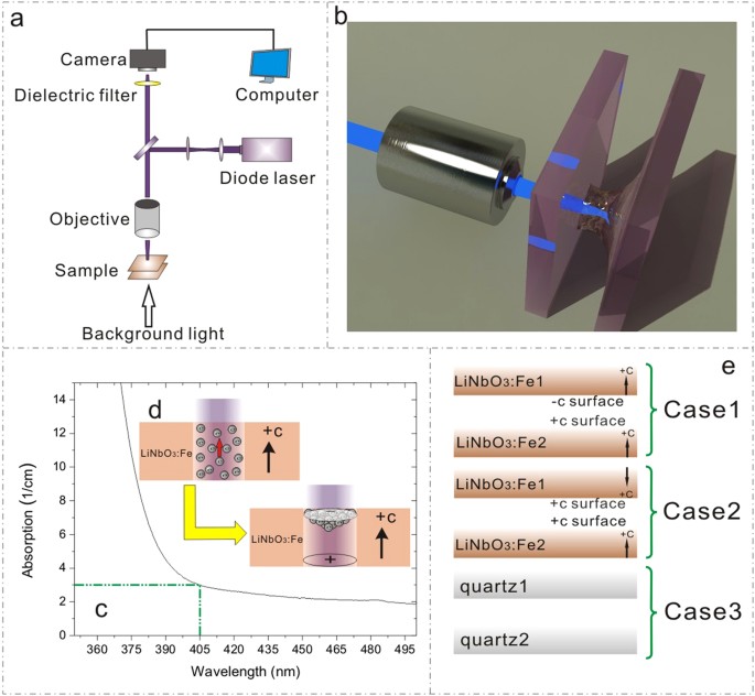
Fe2O3). The thickness of each sample is about 0.5 mm. The experimental setup for observing the behaviours of oil microdroplet under sandwich configuration is shown in Fig. 1(a). The laser
beam (405 nm, CniLaser) was focused by a microscope objective on the sandwich structure and the bottom substrate was used as the base of a liquid reservoir. A camera was used for capturing
the dynamic process with the white light used as a background. The two substrates were fixed on two linear motorized stages where the grating rulers were equipped (not shown in Fig. 1(a)).
The distance between the two sandwich substrates can be adjusted by the motion controller. In our work, two combinations of sandwich substrates were adopted (Fig. 1(e)): +c to −c-surface
(Case 1) and +c to +c-surface (Case 2). Distinct behaviours of the dielectric liquid were observed in the two cases. In order to rule out the possibility that the liquid behaviours are due
to the laser-induced heating of dielectric liquid, another combination of two quartz substrates (Case 3) was also tried as a control experiment. Sample preparation and experimental
procedures are as follows: substrates were firstly sonicated in ethanol for 20 min and then in deionized water for 20 min. After cleaning and drying, dielectric liquid (transformer oil) was
spread out as a thin film on the bottom substrate. Then, two substrates were attached to linear motorized stages, with the distance between them being adjusted to be about 25 μm. When the
laser beam is applied to the substrates, the oil film will be governed by DEP force and the microdroplet can be generated in the form of liquid bridge and manipulated in multimode in the gap
of the two substrates. In our experiment, the medium in the gap (outside the oil drop) is air. RESULTS AND DISCUSSION THE GENERAL PRINCIPLE Dopant Fe can introduce electron traps
(FeLi2+/3+) in the LN lattice and induce a strong absorption in the Visible range. Figure 1(c) shows the UV-Vis absorption spectra of LN:Fe samples used in this work and the absorption at
405 nm was measured to be around 3.0 cm−1. Under the illumination, the electrons can be easily photo-excited from Fe2+/3+ traps and they may be transported by both diffusion and photovoltaic
fields30. In LN:Fe, the dominating charge transport mechanism is the photovoltaic (or photogalvanic) effect29. The strong anisotropy of this effect results in much larger photovoltaic
currents parallel to the polar c axis than perpendicular to it (see Fig. 1(d)). The photovoltaic current density (Jpv) can be described by Jpv = GαI, where G is the Glass constant, α the
absorption and I the laser intensity29,31,32. Under the illumination, the photo-excited electrons are easily accumulated in the +c surface of LN:Fe, leaving a large amount of positive
charges in the −c surface (see Fig. 1(d)). The preferential accumulation of photo- excited electrons in +c surface has been used for selective Ag nano-particle deposition33 or
proton-exchange on LN surface34. Due to the accumulation of photo-excited electrons, strong inhomogeneous electrostatic field comes into being at the LN surface. Under this electrostatic
field, the dielectric liquid will be polarized and moves, governed by the DEP force, toward the place where the maximum of the electrostatic field is located35. The continuing influx of the
dielectric liquid will raise the local liquid level and lead to the rounded liquid meniscus. If the two substrates are sufficiently close, the rounded liquid meniscus may touch the top
substrate and a microdroplet generates in the form of liquid bridge (see Fig. 1(b)). MICRODROPLET GENERATION The two combinations of c-cut Fe-LN substrates were tried: +c to −c surface (Case
1) and +c to +c surface (Case 2). We found that the dynamic processes of microdroplet generation under the same irradiation intensity are quite different in these two cases. As shown in
Fig. 2(a) for the Case 1, a solid circle appears at the laser spot and it becomes increasingly obvious and finally turns into a microdroplet (in the form of liquid bridge). However, in the
Case 2 (see Fig. 2(b)) concentric circles rather than a solid circle are observed before the microdroplet formation. The existence of concentric circles indicates the complexity of the
microdroplet generation in the Case 2. For comparison, the result of two quartz substrates (Case 3) was shown in Fig. 2(c). Neither solid nor concerntric circles are observed, revealing that
the dielectric liquid behaviours are indeed connected with the photo-induced effect of LN:Fe substrates. In order to check the statistical significance of the distinct behaviours in the
Case 1 and Case 2, we tried the microdroplet generation tens of times and found that the experimental reproducibility is quite good. Figure 2 (j,k) show five results selected randomly for
the Case 1 and Case 2, respectively. The statistical significance (P < 0.05) can be guaranteed in our experiments. The features shown by the above results can be connected with the
electrostatic field distribution. According to the photogalvanic effect29, photo-excited electrons accumulate in the illumination region of +c surface while the positive charges are left at
−c surface36,37. Charges at each substrate surface can be regarded as an independent source of electrostatic field and the behaviours of the dielectric liquid should be governed by the
superposed field. In order to better understand the microdroplet behaviours in the sandwich structure, we simulated the electrostatic field (vector norm) in both cases by using the
finite-element model. A 25-μm gap between the two substrates was used for simulations. Assuming the laser intensity at the focus follows the Gaussian distribution and neglecting the
diffusion effect of the photo-exited electrons at the surface37, the surface charge density σ can be given by σ = δtJpv = δtGαI(x, y) = δtGαI0Exp[−2(x2 + y2)/ω2]20, where δt is the
accumulation duration, I0 the maximum intensity and ω the spot size of the beam waist at the focus. It is worth noting that the incident laser power P equals to the integration of the I(x,
y) over the illumination area and the average intensity IA at the focus could be given approximately as IA = P/πω2, where the ω is estimated to be 50 μm. The diffusion of the photo-exited
electrons can be neglected if the microdroplet generation is completed in very short time, i.e. the accumulation duration δt for photo-excited electrons is quite short. As shown in Fig.
3(b), the microdroplet generation is finished in a short δt of 1 s at the illumination condition of IA = 150 mW/mm2 (or P = 1.18 mW) in the Case 1. The Glass constant at 405 nm is estimated
to be 3.3 pAcm/mW31 and the absorption α at 405 nm is measured to be approximately 3.0 cm−1. Figure 2(d,f,g,i) show the simulation results of the electrostatic field (vector norm)
distribution inside the gap by using the parameters: δt = 1 s, P = 1.18 mW, ω = 50 μm, G = 3.3 pAcm/mW and α = 3.0 cm−1 for the Case 1 and Case 2, respectively. Among them, (d), (g) and (f),
(i) correspond to the top view (x-y plane) and the side view (z-y plane), respectively. Herein, the z-axis is parallel with the c-axis of LN. It can be clearly seen that the main difference
between the two cases is the spatial position of the maximum of the electrostatic field: it is located at the center of the illuminated area in the Case 1 while it appears on the circle
edge deviating from the center in the Case 2. As mentioned above, the rising of the liquid level at the location of the maximal electrostatic field may lead to the rounded liquid meniscus.
In the Case 1, the rounded liquid meniscus at the center (peak-like profile in Fig. 2(e)) is observed as a solid circle in Fig. 2(a). However, in the Case 2 the rising of the liquid level
happens at the circle edge (volcano-like profile in Fig. 2(h)) rather than at the center. Consequently, we observed the concentric circles before the final formation of liquid bridge.
Concerning the behaviours of electrified fluid, the most famous phenomena are about its meniscus evolution and the fluid jetting, which are firstly reported by G. Taylor _et al_.38.
Recently, E.O. Elele _et al_. have studied the evolution of the drop meniscus from a rounded shape to a cone under the electrical field39. In their work, the balance of the capillary and
electric pressures in the meniscus was used to give Ea~(2γ/ε0R)1/2, where Ea is the electrostatic field in the air, γ the surface tension, R the radius of meniscus curvature and ε0 the
dielectric constant of surrounding media38,39,40. Considering the geometry in the Case 1, the R could be calculated roughly through the relationship r2 + (R − H + h)2 = R2, given the known
r, h and H. From Fig. 2(a,j), the r is estimated to be 27 μm in the Case 1. The H and h are about 25 and 8 μm. In addition, the γ of the transformer oil is estimated to be 0.04 N/m. By using
the above parameters, Ea required by the microdroplet generation is calculated to be ~1.7 × 10⁷ V/m, which is in good agreement with the magnitude order of the simulated electrostatic field
(1 ~ 2.5 × 10⁷ V/m) inside the gap. In fact, the photovoltaic open circuit field Ephv could easily reach the value of 107 V/m, as already reported by many researchers29,30,31. The
difference between the Case 1 and 2 can also be reflected through the comparison of the time required by the microdroplet generation (i.e. the accumulation duration δt). The dependences of
the accumulation duration δt on the average intensity IA are shown in Fig. 3(a,b) for both cases. It can be seen in both figures that the microdroplet generation in the Case 1 requires much
less time than that in the Case 2. As shown in Fig. 2, the electrostatic field (δt = 1 s) in the Case 1 is much higher than that in the Case 2. In other words, the accumulation duration of
δt = 1 s is insufficient for the microdroplet generation in the Case 2. As a matter of fact, it takes δt = 9 s in the Case 2 to reach the electrostatic field required by the microdroplet
generation. Figure 3(a) shows the increasing irradiation intensity IA can accelerate the microdroplet generation for both cases. For inducing the electrostatic field required by the
microdroplet generation, a critical surface charge density has to be reached. Since the surface charge density σ is proportional to δtGαI, increasing the irradiation intensity may shorten
the accumulation duration δt. However, Fig. 3(b), which contains the data in the range of high intensity, shows that the microdroplet generation in the Case 2 may be slowed down by the
increase of the irradiation intensity IA. The inset image of Fig. 3(b) shows the dynamic process of the microdroplet generation (Case 2) under the intensity IA of 674.2 mW/mm2. The
microdroplet generation starts to slow down just under this intensity. It can be clearly seen that the inner one of the concentric circles changes its size repeatedly, prolonging the final
formation of the liquid bridge. The unexpected slowing-down of the microdroplet generation in the Case 2 has to be connected to its special superposed electrostatic field. If we just focus
on the vertical component (Ez) of the electrostatic field (see Fig. 4), one significant difference between the Case 1 and 2 can be found: the whole electrostatic field in the Case 1 has the
same direction (see the blue region inside the gap in Fig. 4(a)) while the electrostatic field in the Case 2 can be divided by the dot line into two parts having opposite directions (see the
slight orange and blue regions inside the gap in Fig. 4(b)). As mentioned above, the rising of the local liquid level may make a part of polarized oil in the blue region cross the dot line
and enter the orange region. However, this part of oil will be affected by the push-back interaction of the reversed electrostatic field in the slight orange region before the oil
polarization is fully aligned to the new electrostatic field direction. This competition may result in a repeated up-and-down (vibration-like) movement of the oil around the dot line.
Moreover, the competition will be enhanced by the increased electrostatic field under the strong irradiation. In other words, the high irradiation intensity may bring the vibration-like
movement to higher frequency, which certainly delays the formation of the stable oil bridge. As a matter of fact, the repeated variation of the inner circle size shown in Fig. 3(c) provides
the best evidence for this vibration-like movement of oil. Therefore, the slowing-down of the microdroplet generation with the increasing irradiation intensity can only happen in the Case 2
but never in the Case 1. Another significant difference between the Case 1 and 2 is concerning the electrostatic fields in the LN substrates (Es) and in the air gap (Ea). Es is lower than Ea
in the Case 1 while Es is higher than Ea in the Case 2. In both cases, the direction of Es is contrary to that of the photovoltaic current Jpv. Higher Es in the Case 2 may induce a drift
current along the opposite direction of Jpv, suppress the charge accumulation in the substrate surface31 and slow down the microdroplet generation under the high-intensity irradiation. As
the matter of fact, the relatively strong Ea in the double-LN-substrate structure (LN-LN structure) is due to the double contribution from the top and bottom LN substrates and the
manipulation force on the microdroplets in this structure is therefore much higher than that in single-LN-substrate structures (LN-glass or LN-plastic structures). In fact, the manipulation
force exerted by single-LN-substrate has a limit due to the existence of the saturation field in LN:Fe31. This limit of the manipulation force is independent of the irradiation parameters
such as intensity and duration. Thus, for further enhancing the manipulation force, another LN substrate has to be added. As compared with the single-LN- substrate structures, the
double-LN-substrate structure is costly and difficult to be fabricated for lab-on-chip devices. However, we have to emphasize that the employment of double-LN-substrate structure can enhance
the manipulation force and therefore benefit the multimodal and efficient microfluidic manipulation in lab-on-chip devices. It should be noted that the intensity loss induced by the
substrate absorption is not considered in the above simulations. In our case, one 0.5-mm-thick LN:Fe sample may cause the intensity loss of ~14%. If it is taken into account, the intensity
reaching the top and bottom substrates will be different and so will the light-induced surface charge densities of the two substrates. This difference (14%) may lead to an asymmetry of the
electrostatic field, but it does not change the basic profile of the electrostatic field distribution. Therefore, any explanation made basing on the above simulation results is still
reliable. MICRODROPLET MANIPULATION Since the microdroplet generation is more efficient in the Case 1 than in the Case 2, the configuration (+c to −c surface) of the Case 1 is adopted in
this work for the further investigation about the microdroplet manipulation. Note that microdroplet manipulation in the Case 2 is more complicated and versatile. The special behaviours of
the microdroplet in this case will be reported in the forthcoming papers. Since the surface charge density σ is proportional to δtGαI, the accumulation duration δt contributes to the
electrostatic field and the DEP force. The local DEP force on the microdroplet is determined by the spatial distribution of the surface charge density that is proportional to the accumulated
irradiation dosage in the history. This is because the space charges, responsible for the DEP force, would not disappear immediately even after the laser is already switched off and its
decay may last from tens of seconds to several hours depending on the local dark conductivity. Therefore, any past irradiation around the microdroplet will be partly preserved in the form of
space charges, contributing to the local DEP force with its strength proportional to the irradiation dosage. In our experimental setup, the simplest method for controlling the irradiation
dosage is to modify the accumulation duration δt, i.e. to change the irradiation time for dot-irradiation or to change the scanning speed for line-irradiation. The inconsecutive
dot-irradiation scheme is firstly adopted for microdroplet manipulation. In Fig. 5(a), three discrete dot-irradiations are preformed one by one around the microdroplet and their irradiation
time is designed to increase gradually from 1 s to 3 s. In this case, the microdroplet is attracted by three irradiated dots sequentially and moves in a line step by step. Figure 5(b) shows
the manipulation of microdroplet under four close dot-irradiations with the dot-irradiation time of ~1 s. It can be seen that the microdroplet is almost fixed at the original place but
deformed from circle shape to parallelogram one. Through the same dot-irradiation scheme, more complicated microdroplet pattern can be achieved in Fig. 5(c), where the Chinese characters “”
“” “” and English letter “H” are made in such a “microdrawing” way. The microdroplet manipulation effect (step-moving or drawing) of the dot-irradiation scheme depends on the distances
between those discrete irradiated dots and their irradiation dosages. Closer dot spaces and irradiation dosages usually result in the “microdrawing” effect. The consecutive line-irradiation
scheme is then tried for microdroplet manipulation. In order to show the movement of the scanning laser spot and the microdroplet trail more intuitively, many representative frames cut from
the original video are pieced together as presented in Fig. 6. The way we prepare the images here is just like the “Panorama mode” of common digital camera and the numbers in the frames
represent the sequence in time. In Fig. 6(a), the microdroplet location is set as the origin of line-irradiation and the laser spot later scanned with an increasing speed (from 120 um/s to
210 um/s). It is found that the microdroplet is firstly stretched out following the scanning trail but it is then drawn back in the same trail. On the contrary, if we start the similar
scanning from a distance and make the laser spot approaching the microdroplet gradually (see Fig. 6(b)), we observe that the microdroplet can be guided by the scanning trail to the origin of
line-irradiation. The whole guiding process is smooth without obvious jam and it takes about 10 s to cover 1.7 mm distance. Figure 6(c,d) show the results of folding-line-irradiation scheme
and the smooth guiding is also achieved. The microdroplet manipulation demonstrated above is concerning the motion of a deformable dielectric fluid particle in a nonuniform electrostatic
field. The theoretical study about this issue has been done by J.Q. Feng41. He showed that the DEP force produced by the nonuniform electrostatic field could induce both deformation and
motion of the dielectric fluid particle. Thus, the magnitude order of the electrostatic field required for moving the oil microdroplet should be comparable to that required by the
microdroplet generation. The exact amplitude of the electrostatic field could be calculated indirectly from the deformation extent of the oil microdroplet, basing on the relationship between
the shape function of fluid particle and the reference electrical field E. Now, the experiments for the systematical investigation of the microdroplet manipulation are still underway. In
addition, oil microdroplets were chosen as the investigation object. However, water microdroplets are more widely used than oil microdroplets in lab-on-chip. Therefore, water microdroplet
related studies are necessary from the practice viewpoint. In fact, we have preformed some experiments on water microdroplets and found the manipulation of water microdroplets on naked LN
substrates much harder than oil microdroplets. Figure 7 shows the dynamic processes of the attempted generation and manipulation for water microdroplet. One can see that no water bridge is
formed inside the gap (see Fig. 7(a)) and no obvious movement of water microdroplet is observed except its slow evaporation due to light-induced thermal effect (see Fig. 7(b)). The
discrepant behaviour between water and oil microdroplets is probably due to the higher conductivity and permittivity of water microdroplets. But we have to point out that, after covering LN
substrate with a thin super hydrophobic film we found the manipulation efficiency of water microdroplets largely increased. Considering the same liquid nature of oil and water, the
preliminary study on dielectrophoretic behaviours of oil microdroplets is beneficial to the following investigation about water microdroplets. The detailed results regarding water
microdroplets will be reported in forthcoming papers. CONCLUSIONS The behaviours of the dielectric microdroplet under LN-based sandwich configuration are investigated in this paper. It is
found that the microdroplet can generate in the form of the liquid bridge inside the LN-based sandwich structure under the action of DEP force and the dynamic process of microdroplet
generation highly depends on the substrate combinations. Dynamic features, including the liquid meniscus profiles and the irradiation-intensity dependences of the time required by the
microdroplet generation, are observed for different combinations and studied basing on the electrostatic-field simulations. The volcano-like liquid meniscus profile and the vibration-like
liquid movement make the combination of +c surface to +c surface (Case 2) more complicated than the combination of +c surface to −c surface (Case 1). Different kinds of the microdroplet
manipulation are also attempted. We suggest that the local DEP force acting on the microdroplet depends on the distribution of the accumulated irradiation dosage. The microdroplet can be
step-moved, deformed or patterned by the inconsecutive dot-irradiation scheme, as well as elastically-stretched out and back or smoothly-guided in a designed pass by the consecutive
line-irradiation scheme. ADDITIONAL INFORMATION HOW TO CITE THIS ARTICLE: Chen, L. _et al_. Dielectrophoretic behaviours of microdroplet sandwiched between LN substrates. _Sci. Rep_. 6,
29166; doi: 10.1038/srep29166 (2016). REFERENCES * Yang, T. et al. An integrated optofluidic device for single-cell sorting driven by mechanical properties. Lab Chip 15, 1262–1266 (2015).
CAS PubMed Google Scholar * Yang, T. et al. Investigation of temperature effect on cell mechanics by optofluidic microchips. Biomedical Optics Express 6, 2991–2996 (2015). Google Scholar
* Bragheri, F. et al. Optofluidic integrated cell sorter fabricated by femtosecond lasers. Lab Chip 12, 3779–3784 (2012). CAS PubMed Google Scholar * Ferraro, P., Grilli, S., Miccio, L.
& Vespini, V. Wettability patterning of lithium niobate substrate by modulating pyroelectric effect to form microarray of sessile droplets. Appl. Phys. Lett. 92, 213107 (2008). ADS
Google Scholar * George, M. W. The origins and the future of microfluidics. Nature 442, 368–373 (2006). Google Scholar * Srinivasan, V., Pamula, V. K. & Fair, R. B. An integrated
digital microfluidic lab-on-a-chip for clinical diagnostics on human physiological fluids. Lab Chip 4, 310–315 (2004). CAS PubMed Google Scholar * Ahn, C. H. et al. Disposable Smart lab
on a chip for point-of-care clinical diagnostics. Proceedings of The Ieee 92, 154–173 (2004). CAS Google Scholar * Chang, K. W., Li, J., Yang, C. H., Shiesh, S. C. & Lee, G. B. An
integrated microfluidic system for measurement of glycated hemoglobin Levels by using an aptamer-antibody assay on magnetic beads. Biosens. Bioelectron. 68, 397–403 (2015). CAS PubMed
Google Scholar * Esch, E. W., Bahinski, A. & Huh, D. Organs-on-chips at the frontiers of drug discovery. Nature Reviews Drug Discovery 14, 248–260 (2015). CAS PubMed PubMed Central
Google Scholar * Skommer, J. & Wlodkowic, D. Successes and future outlook for microfluidics-based cardiovascular drug discovery. Experte Opinion on Drug Discovery 10, 231–244 (2015).
CAS Google Scholar * Moraes, C. The Discovery Channel: microfluidics and microengineered systems in drug screening. Integrative Biology 7, 285–288 (2015). PubMed Google Scholar * Muir,
A. C., Mailis, S. & Eason, R. W. Ultraviolet laser-induced submicron spatially resolved superhydrophilicity on single crystal lithium niobate surfaces. Journal of Applied Physics 101,
104916 (2007). ADS Google Scholar * Esseling, M., Holtmann, F., Woerdemann, M. & Denz, C. Two-dimensional dielectrophoretic particle trapping in a hybrid crystal/PDMS-system. Opt.
Express 18, 17404–17411 (2010). ADS CAS PubMed Google Scholar * Glaesener, S., Esseling, M. & Denz, C. Multiplexing and switching of virtual electrodes in optoelectronic tweezers
based on lithium niobate. Opt. Lett. 37, 3744–3746 (2012). ADS CAS PubMed Google Scholar * Esseling, M., Zaltron, A., Sada, C. & Denz, C. Charge sensor and particle trap based on
z-cut lithium niobate. Appl. Phys. Lett. 103, 61115 (2013). Google Scholar * Esseling, M. et al. Highly reduced iron-doped lithium niobate for optoelectronic tweezers. Appl. Phys. B 113,
191–197 (2013). ADS CAS Google Scholar * Esseling, M., Zaltron, A., Horn, W. & Denz, C. Optofluidic droplet router. Laser and Photonics reviews 9, 98–104 (2015). ADS CAS Google
Scholar * Villarroel, J. et al. Photovoltaic versus optical tweezers. Opt. Express 19, 24320 (2011). ADS CAS PubMed Google Scholar * Arregui, C. et al. Optoelectronic tweezers under
arbitrary illumination patterns: theoretical simulations and comparison to experiment. Opt. Express 22, 29099 (2014). ADS PubMed Google Scholar * Munoz-Martinez, J. F. et al. Efficient
photo-induced dielectrophoretic particle trapping on Fe:LiNbO3 for arbitrary two dimensional patterning. Optical Materials Express 5, 1137–1146 (2015). ADS Google Scholar * Munoz-Martinez,
J. F. et al. Diffractive optical devices produced by light-assisted trapping of nanoparticles. Opt. Lett. 41, 432–435 (2016). ADS CAS PubMed Google Scholar * Carrascosa, M.,
Garcia-Cabanes, A., Jubera, M., Ramiro, J. B. & Agullo-Lopez, F. LiNbO3: A photovoltaic substrate for massive parallel manipulation and patterning of nano-objects. Appl. Phys. Rev. 2,
040605 (2015). Google Scholar * Jubera, M., Elvira, I., García-Cabañes, A., Bella, J. L. & Carrascosa, M. Trapping and patterning of biological objects using photovoltaic tweezers.
Appl. Phys. Lett. 108, 023703 (2016). ADS Google Scholar * Nili, H. & Green, N. G. Higher-order dielectrophoresis of nonspherical particles. Physical Review E 89, 063302 (2014). ADS
Google Scholar * Kumar, A., Williams, S. J., Chuang, H. S., Greend, N. G. & Wereleye, S. T. Hybrid opto-electric manipulation in microfluidics-opportunities and challenges. Lab Chip 11,
2135–2148 (2011). CAS PubMed Google Scholar * Thomas, R. S., Morgan, H. & Green, N. G. Negative DEP traps for single cell immobilisation. Lab Chip 9, 1534–1540 (2009). CAS PubMed
Google Scholar * Sun, T., Morgan, H. & Green, N. G. Analytical solutions of the dielectrophoretic and travelling wave forces generated by interdigitated electrode arrays. Journal of
Physics: Conference Series 142, 012011 (2008). Google Scholar * Yunus, N. A. M. & Green, N. G. Continuous separation of submicron particles using angled electrodes. Journal of Physics:
Conference Series 142, 012068 (2008). Google Scholar * Schirmer, O. F., Imlau, M. & Merschjann, C. Bulk photovoltaic effect of LiNbO3:Fe and its small-polaron-based microscopic
interpretation. Physical Review B 83, 165106 (2011). ADS Google Scholar * Buse, K. Light-induced charge transport processes in photorefractive crystals I: Models and experimental methods.
Appl. Phys. B 64, 273–291 (1997). ADS CAS Google Scholar * Krätzig, E. & Kurz, H. Photorefractive and Photovoltaic Effects in Doped LiNbO3 . Optica Acta: International Journal of
Optics 24, 475–482 (1977). Google Scholar * Glass, A. M., von der Linde, D. & Negran, T. J. High-voltage bulk photovoltaic effect and the photorefractive process in LiNbO3 . Appl. Phys.
Lett. 25, 233–235 (1974). ADS CAS Google Scholar * Liu, X., Kitamura, K., Terabe, K., Hatano, H. & Ohashi, N. Photocatalytic nanoparticle deposition on LiNbO3 nanodomain patterns via
photovoltaic effect. Appl. Phys. Lett. 91, 044101 (2007). ADS Google Scholar * Liang, G. et al. Photo-assisted proton exchange and chemical etching on Fe-doped lithium niobate crystals.
Opt. Express 23, 19–25 (2015). ADS PubMed Google Scholar * Pohl, H. A. Some Effects of Nonuniform Fields on Dielectrics. Journal of Applied Physics 29, 1182 (1958). ADS Google Scholar *
Liu, X., Hatano, H., Takekawa, S., Ohuchi, F. & Kitamura, K. Patterning of silver nanoparticles on visible light-sensitive Mn-doped lithium niobate photogalvanic crystals. Appl. Phys.
Lett. 99, 053102 (2011). ADS Google Scholar * Jia, F. et al. Photoinduced Ag-nanoparticle deposition on Fe-doped lithium niobate crystals. Optical Materials Express 4, 359–365 (2014). ADS
CAS Google Scholar * Taylor, G. Disintegration of water drops in electric field. Proc. R. Soc. Lond., Ser. A 280, 383–397 (1964). ADS MATH Google Scholar * Elele, E. O., Shen, Y.,
Pettit, D. R. & Khusid, B. Detection of a dynamic cone-shaped meniscus on the surface of fluids in electric fields. Phys. Rev. Lett. 114, 054501 (2015). ADS PubMed Google Scholar *
Wang, Q., Suo, Z. & Zhao, X. Bursting drops in solid dielectrics caused by high voltages. Nat. Commun. 3, 1157 (2012). ADS PubMed Google Scholar * Feng, J. Q. Dielectrophoresis of a
deformable fluid particle in a nonuniform electric field. Physical Review E 54, 4438–4441 (1996). ADS CAS Google Scholar Download references ACKNOWLEDGEMENTS We thank the referees for
their valuable comments. This work is partly supported by NSFC (No. 61108060), EYRF of HeBei EDP (No. YQ2013029), Key Project of MOE (No. 212016), Project-sponsored by SRF for ROS of MOE
(2012), Hebei NSF (No. F2013202153) and SOCSF of MPC (No. CG2013003002). AUTHOR INFORMATION AUTHORS AND AFFILIATIONS * School of Materials Science and Engineering, Hebei Engineering
Laboratory of Photoelectronic Functional Crystals, Hebei University of Technology, Tianjin, 300130, China Lipin Chen, Shaobei Li, Bolin Fan, Wenbo Yan, Donghui Wang, Hongjian Chen, Dechao
Ban & Shihao Sun * Tianjin Urban Construction Institute, Tianjin, 300384, China Lihong Shi Authors * Lipin Chen View author publications You can also search for this author inPubMed
Google Scholar * Shaobei Li View author publications You can also search for this author inPubMed Google Scholar * Bolin Fan View author publications You can also search for this author
inPubMed Google Scholar * Wenbo Yan View author publications You can also search for this author inPubMed Google Scholar * Donghui Wang View author publications You can also search for this
author inPubMed Google Scholar * Lihong Shi View author publications You can also search for this author inPubMed Google Scholar * Hongjian Chen View author publications You can also search
for this author inPubMed Google Scholar * Dechao Ban View author publications You can also search for this author inPubMed Google Scholar * Shihao Sun View author publications You can also
search for this author inPubMed Google Scholar CONTRIBUTIONS W.Y. and L.C. proposed the idea and wrote the main manuscript text. L.C. performed the experiments. S.L., B.F. and L.S. analyzed
and interpreted the data. L.C., D.W., H.C., D.B. and S.S. prepared the figures. All authors reviewed the manuscript. ETHICS DECLARATIONS COMPETING INTERESTS The authors declare no competing
financial interests. RIGHTS AND PERMISSIONS This work is licensed under a Creative Commons Attribution 4.0 International License. The images or other third party material in this article are
included in the article’s Creative Commons license, unless indicated otherwise in the credit line; if the material is not included under the Creative Commons license, users will need to
obtain permission from the license holder to reproduce the material. To view a copy of this license, visit http://creativecommons.org/licenses/by/4.0/ Reprints and permissions ABOUT THIS
ARTICLE CITE THIS ARTICLE Chen, L., Li, S., Fan, B. _et al._ Dielectrophoretic behaviours of microdroplet sandwiched between LN substrates. _Sci Rep_ 6, 29166 (2016).
https://doi.org/10.1038/srep29166 Download citation * Received: 05 January 2016 * Accepted: 16 June 2016 * Published: 07 July 2016 * DOI: https://doi.org/10.1038/srep29166 SHARE THIS ARTICLE
Anyone you share the following link with will be able to read this content: Get shareable link Sorry, a shareable link is not currently available for this article. Copy to clipboard
Provided by the Springer Nature SharedIt content-sharing initiative