- Select a language for the TTS:
- UK English Female
- UK English Male
- US English Female
- US English Male
- Australian Female
- Australian Male
- Language selected: (auto detect) - EN
Play all audios:
ABSTRACT Plasma polymerized nanoparticles (PPN) formed in plasma reactors have been considered undesirable in technological applications. More recently however, PPN were proposed as a new
class of multifunctional nanocarriers for drug delivery. Therefore, synthesis of PPN requires cost-effective collection strategies that maximize yield and improve reproducibility. This work
shows that the collection of PPN in dusty plasmas is modulated by modifying the geometry of substrates from planar to well-shaped collectors. The electric field profile around the wells acts
as an electrostatic lens, concentrating nanoparticles and significantly bolstering process yield. The aggregation of PPN is governed by a balance between plasma expansion throughout the
wells, inter-particle repulsion, particle size and density. PPN are readily dispersed in aqueous solution yielding monodisperse populations. The use of a disposable well-shape collector
provides a cost-effective nanoparticle collection approach that can be adopted in a wide range of plasma polymerization configurations without the need for reactor re-design. SIMILAR CONTENT
BEING VIEWED BY OTHERS NANOSCALE PLASMA-ACTIVATED AEROSOL GENERATION FOR IN SITU SURFACE PATHOGEN DISINFECTION Article Open access 14 April 2022 NANOPARTICLES SYNTHESIS IN MICROWAVE
PLASMAS: PECULIARITIES AND COMPREHENSIVE INSIGHT Article Open access 26 February 2024 THE HIGH-THROUGHPUT ATOMIZATION OF POLYMER SOLUTIONS FOR FIBER SYNTHESIS IN A SINGLE STEP AIDED WITH
CORONA IONIZERS Article Open access 03 August 2023 INTRODUCTION Plasma polymerization (PP)1,2 has been established as a preferred surface deposition platform for technological and biomedical
applications3,4,5,6,7,8. The plasma reactive environment activates monomers into building blocks that polymerize and diffuse toward the plasma boundaries, resulting in the deposition of
thin films with modulated properties, i.e., surface polymerization. A far less explored, often avoided, domain of reactive PP is manifested in some hydrocarbons9, fluorocarbons10, or
silanes11,12 discharges, where surface polymerization occurs simultaneously with plasma bulk polymerization, i.e., dusty plasmas13,14,15. Ionization of acetylene in the plasma for instance,
triggers a continuous formation of carbonaceous nanoclusters that aggregate to form charged particulates in the plasma volume. The formation of PP nanoparticles (PPN) plays a great role in
the fundamental processes governing the discharge15. The electron density and temperature, floating potential and emission intensity oscillate in discharges sustained in dust-forming
plasmas14,16. This long-time scale oscillatory phenomenon is related with changes to the spatial distribution of plasma dust and concomitant with its formation and subsequent removal from
reactors. The growth and subsequent surface deposition of PPN represents a source of contamination in the synthesis of microelectronic components17, or tokamaks used for nuclear fusion
research18,19. In these processes, the discharge characteristics are significantly modified upon formation of PPN, ultimately reducing sample output and process efficiency. More recently,
however, carbon-based PPN were recognized as versatile nanocarriers able to deliver biofunctional cargo without inducing cytotoxicity at therapeutic concentrations20. PPN are formed in
acetylene-based dusty plasmas through assembly of reactive carbonaceous nanoclusters into spherical nanoparticles with modulated physical and chemical properties. The surface of PPN is
reactive, a property inherited from the nanoclusters formed by plasma radical-chain polymerization. Functional moieties preserved on the surface of PPN are readily ionizable in solution upon
modulation of pH, which enables fine tuning of the nanoparticle surface charge and enhances stability in solution. PPN spontaneously immobilize a wide range of clinically relevant
biomolecules by one-step incubation in aqueous solution20. These findings propose PPN as a new class of cost-effective nanoparticles for use in a wide range of applications in nanomedicine.
To address current demands for clinical use, nanoparticles should be made of a biocompatible material that is easy to functionalize21. The synthesis process also needs to be scalable,
cost-effective, and reproducible, while simultaneously allowing an easy modulation of the nanoparticle properties. PP of nanoparticles in dusty plasmas provides a viable synthesis platform,
but the development of high yield and efficient collection strategies that prevent nanoparticle aggregation have not yet been reported. Importantly, the nanoparticle collector should allow a
straightforward post-synthesis manipulation of the nanoparticles for subsequent dispersion in solution. Ideally, the process should be optimized to reduce surface polymerization and enhance
bulk polymerization, hence maximizing nanoparticle collection while inhibiting coating formation. The use of electrically biased “nanolens” arrays has been efficient in controlling the
dynamics and collection of small analytes for sensing applications22. However, this technique would not be suitable in dusty plasma environments for high yield collection of nanoparticles
necessary for biomedical applications. The bulk of research in the field of dusty plasmas has combined modeling and experimental tools to understand the formation, growth, and charging
mechanisms of dust particles23, ultimately providing strategies towards their elimination or removal from reactors and particularly useful in the context of nuclear fusion devices19 and in
thin-film manufacturing industries14,24, where dust formation deteriorates process efficiency. Active manipulation of plasma dust particles has been achieved by the application external
forces. For instance, magnetic fields are beneficial in controlling the dynamics of particles in dusty plasmas, allowing their confinement at different positions in reactors25. Electrostatic
probes that function as “plasma vacuum cleaners” can also effectively manipulate the trajectories of charged particles enabling their removal26. Thermoelectric Peltier elements27 may also
be used to increase the thermophoretic force and drive dust particles towards surfaces in a reactor. The synthesis and collection of silicon-based, non-spherical particles at high mass rates
(~2 g/h) has been also demonstrated from organosilicon precursors in continuous downstream plasma reactor configurations12. However, most collection strategies were not developed envisaging
the use of plasma dust for nanomedicine and are usually characterized by low nanoparticle yield, size polydispersity or irreversible aggregation. Although these approaches are mostly
efficient to remove plasma dust contaminants, they would require specialized equipment (power supplies, vacuum feedthroughs, etc.) that entail modification of pre-existing plasma chambers or
otherwise increase the cost and design complexity in the build of new reactors. Invasive manipulation typically results in a modification of the properties of nanoparticles28, representing
an extra degree of complexity in the synthesis process. The potential of PPN as multifunctional nanocarriers, collected using external manipulation approaches has not yet been demonstrated.
This work shows that the assembly and collection of PPN in dusty plasmas can be passively modulated by the geometry of the substrate. The collection of PPN dusty plasmas can be achieved by
placing commercially available polystyrene well plates on a floating electrode downstream a radiofrequency (rf) electrode. The number of PPN collected in the wells is strikingly enhanced
compared with that collected on a flat substrate, as widely adopted in the deposition of PP coatings. Furthermore, PPN aggregation and yield is controlled by the aspect ratio of the
collector (_a_ = _h_well/_r_well, where _h_well and _r_well are the well height and radius, respectively. Aggregation of PPN for instance, is significantly suppressed by particle–particle
Coulomb repulsion throughout the entire length of lower aspect ratio wells (_a_ ≤ 1.6) at a constant _h_well = 17.4 mm but also for higher aspect ratios (e.g., _a_ = 3.3) by adopting
significantly shorter wells (i.e., _h_well ≤ 10.7 mm). The nanoparticle collection method reported here allows a non-invasive, highly customizable, and efficient collection of PPN, enabling
the use of pre-existing PP systems currently used for coating deposition without the need for external manipulation and reactor re-design. Following synthesis, PPN can be dispersed in
aqueous solution directly in the wells and for use as nanocarriers without the requirement for further purification steps. RESULTS TWO-DIMENSIONAL VERSUS THREE-DIMENSIONAL SUBSTRATES The
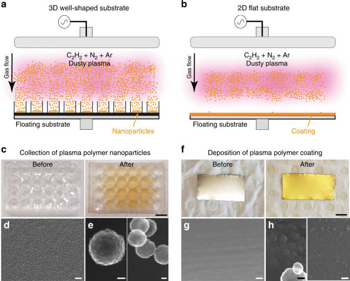
collection of PPN in C2H2/N2/Ar capacitively coupled rf dusty plasmas (see Methods) was carried out using a three-dimensional (3D) entrapment device comprising an assembly of wells as shown
in Fig. 1a. The plurality of wells is placed on top of a floating substrate holder (bottom electrode) to entrap PPN falling within the boundaries of each well. The 3D collection device can
be emulated, for instance, by commercially available tissue culture plates, comprising an array of wells with varying number and aspect ratios. Experiments were also carried out on stainless
steel (SS) sheets without the 3D collector as shown in Fig. 1b, enabling a direct comparison with samples obtained under a standard flat substrate geometry, which is widely adopted in the
deposition of plasma polymer thin-film coatings. The collection efficiency of the well plates was first exemplified using 8.5 cm × 12.7 cm polystyrene tissue culture plates, containing 24
wells distributed in a well matrix of four rows (A–D) × 6 columns (1–6). The depth and surface area of each well was 1.7 cm and 2 cm2, respectively. Exposure of the well plate to the dusty
plasma for 7 min (corresponding to five complete PPN growth cycles) resulted in a significant change in the plate appearance, as shown in Fig. 1c by the deposition of a powder-like brown
material. The collection of nanoparticles was confirmed by placing SS sheets on the bottom of wells, which allowed retrieval of as-synthesized PPN suitable for secondary electron microscopy
(SEM). For the purpose of imaging, the plasma was set to run for a single growth cycle (i.e., 80 s) to avoid superimposition of multiple PPN generations. The SS surface was covered by a
large number of spherical nanoparticles (Fig. 1d) featuring a cauliflower-like surface topography (Fig. 1e). The nanoparticles were uniformly distributed throughout the SS sheets, covering
29% of its surface and were mostly arranged in aggregates formed by the assembly of 3 to up to 20 particles. Interestingly, coating deposition was not observed on surfaces placed inside the
wells, suggesting that surface polymerization is inhibited on the bottom of the wells. This collection method thus yields pure nanoparticle samples free of coatings. In contrast, plasma
polymer coatings were obtained under the same discharge parameters on SS sheets (Fig. 1f) placed on the floating substrate holder in a flat configuration (i.e., without the plate collector).
The diffusion and subsequent surface polymerization of active species from the plasma rendered a uniform gold-colored coating on the substrate. The coating morphology (Fig. 1g) suggests
that surface PP occurs in localized islands that subsequently merge and conformally cover the underlying substrate. Nanoparticle deposition on the flat substrates was virtually negligible,
covering <1% of the surface (Fig. 1g and h). MODULATION OF NANOPARTICLE COLLECTION WITH INPUT POWER AND PRESSURE The collection of PPN was carried out with independent variation of rf
input power (Fig. 2a) and working pressure (Fig. 2b). An increase in power yielded larger PPN aggregates at a fixed pressure of 150 mTorr. The maximum aggregate size ranged from 1850 nm at
50 W to 5950 nm and 9564 nm at 75 W and 100 W, respectively (Fig. 2c). The median size of individual PPN (non-aggregated) decreased from 250 nm at 50 W to 150 nm and 146 nm at 75 W and 100
W, respectively. The formation of larger aggregates at higher input power correlates with an increase in PPN number density in the plasma. Accordingly, PPN yield was enhanced from 31 mg/h at
50 W to 86 mg/h and 88 mg/h at 75 W and 100 W, respectively (Fig. 2d). The formation of plasma dust is characterized by oscillations in the discharge radiation, as a result of the plasma
response to the formation, growth, and removal of the particles from the plasma inside the chamber. Optical emission spectroscopy carried out during the synthesis process recorded the
temporal profile of the plasma emission intensity, allowing quantification of the number of growth cycles in each synthesis run. The period of the oscillations, hence the duration of the PPN
formation cycle, decreased with increasing power from 90 s at 50 W to 52 s and 40 s at 75 W and 100 W, respectively (Fig. 2e). Aggregation and yield of collected PPN was also modulated by
the discharge working pressure (Fig. 2b), which was adjusted by tuning the pumping speed to maintain a constant total gas flow rate throughout the set of experiments shown in this work. For
this study, we chose an input power of 100 W since it allowed screening of a wider pressure range at which PPN can be formed (80 mTorr – 250 mTorr at 100 W vs 80 mTorr – 180 mTorr at 50 W).
PPN yield was significantly reduced at 100 mTorr (17 mg/h) and 200 mTorr (22 mg/h) while aggregation was minimal at 200 mTorr. The duration of the oscillations in the plasma emission
intensity decreased with increasing discharge pressure (Fig. 2f). At lower pressure, the mean-free path between particles (electrons, neutrals, and ions) increases due to a reduction of the
particle number density. This reduces the yield of PPN due to an overall decrease in the collision probability within the plasma. Moreover, a reduction in the activation of precursor
molecules could also be driven by a decrease of the particle residence time in the reactor, since an enhancement of the pumping efficiency is required to lower the pressure while preserving
a constant gas mass flow rate. At higher pressure but without an increase in power, the density of gas molecules increases in excess, reducing precursor activation, hence PPN yield, due to
an overall decrease in the power per molecule unit mass. We also observed an increase in coating deposition in other regions of the plasma chamber (data not shown), suggesting a transition
in the discharge from bulk polymerization to surface polymerization. NANOPARTICLE DISTRIBUTION IN COLLECTOR WELLS The collector plates were then exposed to dusty plasmas for increasing time
periods to establish if the proposed collection method facilitates higher nanoparticle yields. Fig. 3a–d shows photographs of the well plates exposed to the dusty plasma for 2, 5, 10, and 15
growth cycles, respectively, for a working pressure of 150 mTorr and input rf power of 50 W (these parameters yielded minimal aggregation of as-synthesized PPN as shown in Fig. 2a and were
chosen throughout this work). The number of cycles trended linearly with the plasma run time (Fig. 3e), and a high coefficient of determination _R_2 = 0.9992 was obtained from a linear
regression to the experimental data. An increasing number of nanoparticles were collected from the reactor with increasing exposure of the plates to the dusty plasma. The density of
nanoparticles is generally greater on the wells located within the central columns (2–5) and particularly higher in rows C and D, positioned closest to the reactor’s center. The spatial
distribution of as-synthesized nanoparticles inside the plates was obtained by ultraviolet/visible (UV/VIS) spectroscopy by measuring the optical density (OD) of each well at a wavelength of
500 nm. For instance, the average OD of the wells increases significantly with the accumulation of larger number of generations of nanoparticles (Fig. 3f). Figure 3g shows a typical OD
spatial distribution map and a horizontal line scan through the center of well (well C4 is shown) for a plate exposed to 15 nanoparticle growth cycles. Up to 85% of the nanoparticles
accumulate within 10 mm of the well center and their distribution feature symmetrical radial density profile along the well’s symmetry axes. The properties of PPN were studied in solution by
dispersing the nanoparticles in water directly from the wells (Fig. 4a–c). A PPN concentration curve was established by measuring the absorbance at 500 nm (Fig. 4d). A high coefficient of
determination (_R_2 = 0.9993) was obtained from a linear regression fit to a wide nanoparticle concentration range (8 × 10⁷–4 × 10¹⁰ PPN/mL). Collection and subsequent dispersion of two
consecutive nanoparticle generations in water yields a population with a hydrodynamic median size of 214 ± 16 nm (Fig. 4e). The size increases, however, with the collection of subsequent
generations of nanoparticles (253 ± 4 nm, 271 ± 15 nm, and 260 ± 3 nm at 5, 10, and 15 growth cycles). Collection and dispersion of fewer nanoparticle generations results in monodisperse
populations as shown in Fig. 4f (PDI = 0.05 ± 0.03 for two growth cycles and PDI = 0.07 ± 0.01 for five growth cycles). Increasing the number of growth cycles broadens the polydispersity
range (PDI = 0.15 ± 0.06 for 10 growth cycles and PDI = 0.13 ± 0.07 for 15 growth cycles), but no significant differences were found between data sets. MODULATION OF NANOPARTICLE COLLECTION
WITH WELL ASPECT RATIO The role of the well height, _h_well, and radius, _r_well, in the collection of PPN was then studied by utilizing collectors with varying number of wells. SEM was
performed on as-synthesized PPN samples collected on Si wafer substrates placed on 6-, 12-, 24-, 48-, and 96-well plates. Plates containing 6–48 wells allow study of the role of _r_well
since _h_well is constant between plates. The 96-well plate is used to establish the influence of a smaller _h_well, but at a similar aspect ratio to the 48-well plate (see Supplementary
Table 1). The presentation of as-synthesized PPN including surface coverage, distribution, and aggregation is strikingly modulated by the well aspect ratio (Fig. 5a). Overall, significant
formation of large aggregates was observed on 24- and 48-well plates. The aggregates were uniformly dispersed on Si substrates, measuring 0.4–2 μm in their longest dimension. Each aggregate
is formed by the assembly of spherical PPN with diameters ranging 200–300 nm. Individual PPN were also found scattered around the surface amid aggregates. The formation of large aggregates
was significantly suppressed on samples collected on 6-, 12-, and particularly 96-well plates. SEM images were analyzed to further quantify the distribution of PPN on the various well plates
(Fig. 5b). All plots are characterized by a sharp rise around 250–360 nm, related to individual, non-aggregated PPN. Overall, the distributions are asymmetric due to the presence of PPN
aggregates of various sizes. Multi-peak deconvolution adopting gaussian profiles was performed to quantify the contribution of individual PPN and aggregates to the overall distribution
envelope. The fitting parameters for each peak, including full width at half maximum (FWHM), peak area and peak centroid, are given in Supplementary Table 2. In each sample group, the first
peak (P1) represents the isolated PPN population, whereas P2 and P3 are generally associated with PPN aggregates of 2 and 3 nanoparticles, respectively. The wide range of FWHM values and
areas obtained for P3, P4, and P5 is related with the different number of PPN in each aggregate, yielding structures of varied geometrical configurations. For instance, elongated aggregates
of up 60 particles were observed on 24- and 48-plate collectors, whereas on the 96-well collector most of the particles were either individual PPN or formed compacted aggregates with no more
than 6–7 particles. The most polydisperse samples were observed on the 24- and 48-well collectors where up to 5 peaks were required to fit the distribution envelope. The highest fraction of
non-aggregated PPN were found on the 12- and 96-well collectors, contributing to 59 and 51% of the total sample, respectively. PPN collected on the 96-well plates, however, formed the most
monodisperse distribution with a FWHM of 30 nm, which was significantly lower than 58 nm obtained in the 12-well plates. More monodisperse samples were characterized by larger individual PPN
with P1 center peaks at 346 nm, 367 nm, and 301 nm for samples collected with the 6-, 12-, and 96-well plates, respectively. PPN collected with the 24- and 48-well plates had P1 center
peaks at 259 nm and 249 nm, respectively. Substrate coverage, measured by SEM image processing and calculated as the ratio between the total PPN footprint and total area of the imaged
substrate, increased with the well aspect ratio (Supplementary Fig. 1), reaching 83% on the 96-well collector plates upon collection of a single generation of PPN (i.e., growth cycle of 80
s). Dispersion of nanoparticles in water yielded monodisperse and stable PPN colloidal populations for all well collectors (Fig. 5c), showing that nanoparticle aggregation is reversible. The
collection efficiency of PPN per unit area of the plate (Supplementary Fig. 2) was similar between samples dispersed from the 6- and 12-well plates, yielding (4.1 ± 0.2) × 106 PPN/mm2 and
(3.6 ± 0.2) × 106 PPN/mm2, respectively. The collection of PPN was significantly enhanced for samples dispersed from the 24-, 48-, and 96-well plates giving yields of (5.1 ± 0.3) × 107 PPN/
mm2, (4.5 ± 0.3) × 107 PPN/mm2, and (3.4 ± 0.2) × 107 PPN/mm2, respectively. DISCUSSION Any explanation for the increased number of PPN entrapped in the wells compared with a flat substrate
configuration (Fig. 1) must consider multiple factors, including particle charge, balance of forces, and plasma–substrate interactions. It is widely accepted that PPN acquire a negative net
charge in a plasma due to preferential diffusion of electrons towards the particles29,30,31. Therefore, the electrostatic force, Fe, plays a fundamental role in the dynamics of PPN and
ultimately their fate inside the reactor. Indeed, electrostatic entrapment of negatively charged PPN in the positive plasma potential is likely responsible for the lack of particles observed
in flat substrates. Dust particles levitate in equilibrium positions above the plasma sheath edge, where Fe is balanced by dragging, thermophoretic, and gravitational forces15. Since the
neutral (Fn) and ion drag (Fi), thermophoretic (Ft) and gravitational forces (Fg), i.e., forces that drag particles towards the plasma boundaries, trend \(\propto r_p^2\), \(\propto r_p^2\),
\(\propto r_p^2\), and \(\propto r_p^3\), respectively32,33 (_r_p is the particle radius), results in Fig. 1 suggest that the vertical component of these forces are overwhelmed by Fe(∝
_r_p) for _r_p < 200 nm (a comprehensive description of the forces acting on plasma dust particles can be found elsewhere29). Fg is expected to be negligible for individual PPN in this
work. This assumption is uniformly consistent with several works on carbonaceous and silane-based dusty plasmas, where gravity is the dominant force only when _r_p > > 1
µm34,35,36,37,38. Here, \(\left| {{\mathbf{F}}_{\mathrm{g}}} \right| = 1.52 \ \times \ 10^{ - 16}\ {\mathrm{N}}\) for _r_p = 125 nm and a mass density of _ρ_p = 1900 kg/m3 for hydrogenated
carbon-nitride materials synthesized in rf discharges39. In the plasma bulk, we estimate \(\left| {{\mathbf{F}}_{\mathrm{t}}} \right|\sim 10^{ - 16} {\mathrm{N}}\) for a measured gas
temperature of 370 K (see Methods), a wall temperature of 300 K and \(\left| {{\mathbf{F}}_{\mathrm{n}}} \right| \le 5 \ \times 10^{ - 16} {\mathrm{N}}\) with \(n_n \approx 4 \times 10^{21}\
m^{ - 3}\) and \(n_p\sim 10^{14}\ m^{ - 3}\) at input power of 50 W and working pressure of 150 mTorr. Here, _n_n and _n_p represent the number density of the neutral gas species and PPN,
respectively. We estimated _n_p by measuring PPN yield obtained in a 24-well plate and considering the volume ratio between the plasma above the plate and the total active plasma. Consistent
with previous works, Fn and Ft are expected to dominate over Fi in the plasma bulk36,37,38, dragging PPN towards the sheath edge above the flat substrate. At the sheath edge, Fe and Fi
increase significantly in magnitude due to an increase in the electric field. We estimate near the plasma sheath edge that \(\left| {{\mathbf{F}}_{\mathrm{n}}} \right|,\left|
{{\mathbf{F}}_{\mathrm{t}}} \right| \, < \, \left| {{\mathbf{F}}_{\mathrm{i}}} \right| \ \le \ \left| {{\mathbf{F}}_{\mathrm{e}}} \right|\sim 5 \times 10^{ - 16} - 10^{ - 15}\
{\mathrm{N}}\) for a calculated electron temperature of \(2.25\;{\mathrm{eV}} \pm 0.5\;{\mathrm{eVa}}\) and electron density range of \(10^{14} - 10^{15}\ m^{ - 3}\) at 50 W and 150
mTorr35,36. Particles levitating in their vertical equilibrium positions close to the plasma sheath are eventually removed from the reactor by the action of Fn and Ft, arising from the gas
flow which moves across the substrate over the edges towards the pumping port (Fig. 6) and temperature gradients. Therefore, only significantly larger particles would reach the substrate by
action of gravity and drag forces. Enhanced collection of PPN in the collector plates is likely driven by two main factors. First, the ability of the positive plasma potential to expand
inside the wells (Fig. 6 and Supplementary Movie 1), facilitating entrapment of PPN. Second, the formation of a plasma sheath around the wells which results in an electric field, Efield,
profile that acts as an “electrostatic converging lens”, concentrating the particles around the central well axis (Fig. 6) at higher well aspect ratios (_a_ ≥ 2.2). This “electrostatic
lensing effect” possibly arises from the Fe acting on particles with a direction perpendicular to and fanning out of the surface of the wells. We expect the magnitude of the electrostatic
force should have a maximum near the well edge where the plasma sheath thickness, _d_sheath, decreases and bends around the top part of the well. The particles, confined by Fe, are trapped
inside as the plasma expands into the wells. The particle density inside the wells is higher closer to the well center axis as particles are pushed by Fe. Particles inside the wells also
experience both downwards Fg, Ft, and Fi forces, the latter with a direction fanning towards the walls but virtually no neutral drag force as the gas cannot move out through a well. Assuming
a uniform charging along the inner walls of the insulating polystyrene wells, particles located along or near the well vertical axis will mostly experience downward Fi, Ft, and Fg forces
which counterbalance the vertical component of Fe. The particles, as they grow, will continue to experience a downward net force, bringing them closer to the bottom of the collector until
they reach an equilibrium position or reach the bottom. Particles further from the central vertical axis experience horizontal Fi and Ft that directs the particles to the closest inner
walls. Therefore, the radial density distribution with increasing amount of PPN towards center of the wells (Fig. 3g) is likely driven by a combination of the electrostatic force lensing
effect and downward particle drag. This hypothesis is also consistent with the increasing number of PPN deposited on the lateral walls closer to the bottom of the low aspect ratio wells
(Supplementary Fig. 3). Therefore, the collection method proposed here efficiently collects plasma dust particles by entrapment, without external manipulation. An inspection of PPN
collected from plates of various well aspect ratios reveals a uniform distribution of aggregates formed by several individual nanoparticles. Although the radius of individual PPN is ≈50–175
nm, aggregates ranged from ~400 nm up to ~2 μm. Given that each spherical PPN acquire a significant negative net charge in the plasma, Coulomb repulsion effectively prevents particle
aggregation40. The formation of large aggregates was reduced on wider wells (6- and 12-well plate collectors) and significantly suppressed on the 96-well plate collectors as shown in Fig.
5a, b. These results suggest that the electrostatic potential between particles prevents their aggregation until they reach the bottom of the wells. Our observations on the 6- and 12-well
plates are consistent with the ability of plasma potential to extend throughout a greater fraction of the wells (Fig. 7a). PPN aggregation is prevented by interparticle electrostatic
repulsion before they reach the bottom of the well due to a reduction of the sheath width. As the particles travel through a great fraction of the wells, while remaining confined in the
plasma, they will continue to grow further due to the diffusion of ions and radicals. This continued growth results in both larger particles (_r_p ≈ 175 nm) and in a more efficient
interparticle electrostatic repulsion as larger particles will continue to build-up more charge in the plasma due to diffusion of electrons. Since the “electrostatic lensing effect” is
significantly mitigated in these wells, particle density around the well center axis is reduced as a result of larger radii of the wells (i.e., 17.7 mm and 11.1 mm in the 6- and 12-well
plates in comparison with 7.2 mm and 5.5 mm in 24- and 48-well plates, respectively). The formation of microclusters in the 24- and 48-well plates (Fig. 5) suggests that interparticle
electrostatic repulsion is no longer effective in preventing particle–particle aggregation inside these wells. The formation of dust particulate aggregates has been previously reported in
the afterglow region of a downstream plasma reactor in silane-based discharges12, suggesting here that the plasma is unable to expand throughout the entire depth of the 24- and 48-well
plates (Fig. 7b). As the electron density decreases downstream of the plasma sheath, the aggregation probability between colliding particles with sufficiently high kinetic energy increases,
since attractive forces between particles (e.g., van-der-Walls, radical sticking, etc) can now overcome the interparticle electrostatic potential40,41. An increase in the vertical component
of the electric field that resists dragging forces in the 96-well plates results in the formation of larger particles (_r_p ≈ 150 nm c.f. those found in the 24- and 48-well plates) and
enhancement of electrostatic repulsion downstream of the plasma sheath along the wells. Therefore, suppression of aggregates observed in samples collected with the 96-well plates (Fig. 7c)
is likely driven by a stronger interparticle Coulomb repulsion. Although PPN formed by volume polymerization are dragged and entrapped inside the wells, coating formation is avoided by
inhibition of surface polymerization on the bottom of the wells. Consequently, PPN are readily dispersed following synthesis directly from the wells to form a monodisperse and stable aqueous
colloidal dispersion. Therefore, this approach eliminates the need for step-wise filtration, purification, and phase separation, which is usually necessary in wet-chemistry nanoparticle
synthesis that require the use of solvents or toxic reagents. After synthesis and dispersion in solution, PPN are transferred into tubes (Fig. 4c) for subsequent use in biomedical
applications. Measurements of the OD (Fig. 4d) of PPN dispersed in solution directly from the wells results in a linear trend over a wide concentration range, allowing ready quantification
of PPN using UV/VIS calibration standards. Since multiple wells are comprised in a single collector plate, the number of wells can be pre-selected according to the amount of PPN necessary
for a given experiment. PPN synthesized in acetylene-based dusty plasma feature a long shelf-life20, allowing the remaining wells to be stored for subsequent needs. Moreover, the collector
plates are sterilized upon exposure to the plasma and can be subsequently sealed under sterile environment for applications that require in vitro or in vivo delivery of PPN. Although further
measurements of the floating potential, electron and ion fluxes around the wells will need to be carried out in future studies, this data may be used to design customized 3D substrates that
further enhance PPN yield. This work shows that the collection of monodisperse, off-the-shelf PPN in dusty plasmas can be significantly improved by replacing a standard flat substrate
geometry with 3D well plate collectors. Although a flat substrate leads to the deposition of a plasma polymer coating with few if any nanoparticles, the well plates prevent coating formation
and efficiently entrap nanoparticles formed in the plasma bulk. High aspect ratio wells (_a_ ≥ 2.2) significantly bolster nanoparticle yield, whereas decreasing the well heights effectively
prevents aggregation between as-synthesized negatively charged particles. PPN can be readily dispersed from the wells in aqueous solution without aggregating, eliminating the need for
further sample processing. The number of nanoparticles in each well can be directly measured before dispersion, allowing pre-selection of wells to be dispersed depending on experiment
demands. The use of disposable multi-well plates in the active plasma provides a controllable, cost-effective, customizable, and efficient collection approach of PPN that can be readily
applied to already-built reactors and pave the way for a nanoparticle synthesis and collection platform compatible with commercial demands. METHODS PPN SYNTHESIS AND COLLECTION NanoP3 were
synthesized in a cylindrical SS capacitively coupled rf reactor as previously reported20. The reactor was pumped down to a base pressure of ~10−6 Torr where C2H2/N2/Ar plasmas were sustained
at a working pressure of 100 mTorr – 200 mTorr at input powers of 50 W, 75 W, or 100 W. The flow rate of C2H2, N2, and Ar was maintained constant at 2 sccm, 10 sccm, and 3 sccm for each
synthesis run. The duration of each run was adjusted according to the number of PPN formation cycles necessary for each experiment, typically between 80 s and 1200 s. The collection of
nanoP3 was carried out in 8.5 cm × 12.7 cm polystyrene tissue culture well plates (Corning, USA) with various number of wells (6, 12, 24, 48, or 96 wells). The plates were placed on the
substrate holder, a floating electrode positioned 10 cm below the rf electrode. Si wafers or SS flat substrates were placed on the bottom of the wells, allowing nanoP3 trapped inside the
wells to be imaged with secondary electron microscopy (SEM). The dimensions of the Si wafers or SS flat substrates were adjusted for each plate to cover the maximum area possible in each
well type while ensuring suitable dimensions that would fit on SEM stubs (1 cm × 1 cm for 6-, 12-, and 24-well plates, 0.7 × 0.7 cm for 48-well plates and 0.4 × 0.4 cm for 96-well plates).
IN SITU OPTICAL EMISSION SPECTROSCOPY The synthesis process was monitored in situ using optical emission spectoscopy to measure the temporal profile of the plasma emission intensity during
the formation of PPN. Spectra with a nominal resolution of 0.014 nm were acquired with an Acton SpectraPro 2750 spectrometer (Princeton Instruments, USA) equipped with a 1200 grooves mm−1
grating, an entrance slit opened at 50 μm and a PI-MAX (Princeton Instruments, USA) intensified charge-coupled device (ICCD) with a 1024 × 1024 pixel array optically coupled with the
spectrometer’s exit plane and a optic fiber in line-of-sight with the region of the plasma immediately above the well plates. The exposure time was 300 μs and 150 consecutive acquisitions
were averaged to maximize the signal-to-noise ratio. The entire optical setup remained unchanged throughout the experiments. Oscillations of the molecular emission band associated with
rotational–vibrational transitions of \({\mathrm{N}}_2^ +\) (0–0) molecular ions from the first negative system (B2Σu → X2Σg) between 389 nm and 392 nm, with a band head centered at 391.64
nm, was used as a surrogate of the period of each PPN growth cycle20. The excitation temperature of argon excited states (assumed to represent the electron temperature) and the rotational
temperature of N2 (assumed to represent the gas temperature) was measured using OES as previously reported5,42. SEM SEM was carried out on as-synthesized PPN using a Zeiss Sigma HD FEG SEM
at an acceleration voltage of 5 kV, a working distance between 8 and 12 mm, pressure of 30 Pa and a 30 μm aperture. DYNAMIC LIGHT SCATTERING Dynamic light scattering was carried out to
measure the hydrodynamic size and concentration of PPN particles dispersed in ultra-pure water directly from the wells. A NanoSight NS300 laser light scattering system was used to determine
the hydrodynamic size distribution and concentration of PPN. Samples (_n_ = 5) were processed at constant flow through the analysis chamber using a nanoparticle tracking system (NanoSight
NTA 3.0) and all measurements were performed at 24 ˚C. The median hydrodynamic size of PPN was confirmed by running samples through a Zetasizer Nano ZS (Malvern Instruments, Germany), which
also measured the distribution polydisperse index. UV-VIS MEASUREMENTS The OD of PPN was measured directly on the wells using a CLARIOstar microplate reader (BMG LABTECH, Germany). IMAGE
PROCESSING—SIZE DISTRIBUTION SEM images were analyzed using Image-Pro Premier (Edition 9.2, 64-bit). The images were segmented using an in-built threshold tool allowing separation between
the PPN and the substrate background. A global threshold constant was chosen for each image based upon intensity values from a bimodal histogram. The measurement data type was selected with
Area, Caliper mean, and Caliper max chosen. Minimum and maximum values of each data type were set to further refine selections by removing outliers resulting from impurities and
irregularities in the image. Nanoparticles on the border of the image were disregarded. We adopted the average Feret diameter43 (Caliper Diameter) to measure the size of PPN and aggregates.
Size histograms were obtained using the multi-peak analysis and fitting tools provided with the OriginLab Pro package. The number of peaks and peak position was first obtained by double
differentiation of the distribution envelope of each data set. Fitting was carried out by adopting a Gaussian profile for each contribution. A non-linear least-square convergence criteria
monitored the error between the original and deconvoluted spectra, imposing relative errors below 10−6. Each peak was allowed to drift ± 20 nm from the peak center defined by the envelope
double differentiation. STATISTICAL ANALYSES Data were reported as mean ± standard deviation (_n_ = 3 unless otherwise indicated). Two-way analysis of variance was performed using GraphPad
Prism (GraphPad Software). Where relevant, statistical significance is indicated in the figures as ns (not significant) (_p_ ≥ 0.05), * (_p_ < 0.05), ** (_p_ < 0.01), *** (_p_ <
0.001), or **** (_p_ < 0.0001). DATA AVAILABILITY The data that support the findings of this work are available from the corresponding author upon reasonable request. REFERENCES * Yasuda,
H. K. _Plasma Polymerization_ (Elsevier Science, Orlando, 2012). Google Scholar * Hynek Biederman, Y. O. _Plasma Polymerization Processes_ (Elsevier, New York, 1992). * Yasuda, H. &
Gazicki, M. Biomedical applications of plasma polymerization and plasma treatment of polymer surfaces. _Biomaterials_ 3, 68–77 (1982). Article Google Scholar * Vanags, L. Z. et al. Plasma
activated coating immobilizes apolipoprotein A-I to stainless steel surfaces in its bioactive form and enhances biocompatibility. _Nanomedicine_ 13, 2141–2150 (2017). Article Google Scholar
* Santos, M. et al. Mechanically robust plasma-activated interfaces optimized for vascular stent applications. _ACS Appl. Mater. Interfaces_ 8, 9635–9650 (2016). Article Google Scholar *
Santos, M., Bilek, M. M. M. & Wise, S. G. Plasma-synthesised carbon-based coatings for cardiovascular applications. _Biosurf. Biotribol._ 1, 146–160 (2015). Article Google Scholar *
Yeo, G. C. et al. Plasma-activated tropoelastin functionalization of zirconium for improved bone cell response. _ACS Biomater. Sci. Eng._ 2, 662–676 (2016). Article Google Scholar * Wise,
S. G. et al. Immobilization of bioactive plasmin reduces the thrombogenicity of metal surfaces. _Colloids Surf. B Biointerfaces_ 136, 944–954 (2015). Article Google Scholar * Winter, J. et
al. Dust formation in Ar/CH4 and Ar/C2 H2 plasmas. _Plasma Sources Sci. Technol._ 18, 034010 (2009). Article ADS Google Scholar * Anderson, H. M., Radovanov, S., Mock, J. L. &
Resnick, P. J. Particles in C2F6-CHF3 and CF4-CHF3 etching plasmas. _Plasma Sources Sci. Technol._ 3, 302 (1994). Article ADS Google Scholar * Stoffels, W. W., Stoffels, E., Kroesen, G.
M. W. & Hoog, F. J. d. Electron density fluctuations in a dusty Ar/SiH4 rf discharge. _J. Appl. Phys._ 78, 4867–4872 (1995). Article ADS Google Scholar * Roth, C., Oberbossel, G.,
Buitrago, E., Heuberger, R. & Rudolf von Rohr, P. Nanoparticle synthesis and growth in a continuous plasma reactor from organosilicon precursors. _Plasma Process. Polym._ 9, 119–134
(2012). Article Google Scholar * Langmuir, I., Found, C. G. & Dittmer, A. F. A new type of electric discharge: the streamer discharge. _Science_ 60, 392–394 (1924). Article ADS
Google Scholar * Bouchoule, A. _Dusty Plasmas: Physics_, Chemistry, _and Technological Impacts in Plasma Processing_ (Wiley, New York, 1999). * Berndt, J. et al. Some aspects of reactive
complex plasmas. _Contri. Plasma Phys._ https://doi.org/10.1002/ctpp.200910016 (2009). Article ADS Google Scholar * Bouchoule, A. Dusty plasmas. _Phys. World_ 6, 47–51 (1993). Article
Google Scholar * Osamu, I. Complex plasma: dusts in plasma. _J. Phys. D Appl. Phys._ 40, R121 (2007). Article Google Scholar * Winter, J. Dust in fusion devices - experimental evidence,
possible sources and consequences. _Plasma Phys. Control. Fusion_ 40, 1201 (1998). Article ADS Google Scholar * Winter, J. Dust in fusion devices - a multi-faceted problem connecting
high- and low-temperature plasma physics. _Plasma Phys. Control. Fusion_ 46, B583–B592 (2004). Article Google Scholar * Santos, M. et al. Plasma synthesis of carbon-based nanocarriers for
linker-free immobilization of bioactive cargo. _ACS Appl. Nano Mater._ 1, 580–594 (2018). Article Google Scholar * Peer, D. et al. Nanocarriers as an emerging platform for cancer therapy.
_Nat. Nano_ 2, 751–760 (2007). Article Google Scholar * Lin, E.-C. et al. Effective collection and detection of airborne species using SERS-based detection and localized electrodynamic
precipitation. _Adv. Mater._ 25, 3554–3559 (2013). Article Google Scholar * Ming, M., Jan, B., Angelo, C. & Annemie, B. New pathways for nanoparticle formation in acetylene dusty
plasmas: a modelling investigation and comparison with experiments. _J. Phys. D Appl. Phys._ 41, 225201 (2008). Article ADS Google Scholar * Boufendi, L. & Bouchoule, A. Industrial
developments of scientific insights in dusty plasmas. _Plasma Sources Sci. T_ 11, A211–A218 (2002). Article ADS Google Scholar * Puttscher, M. & Melzer, A. Dust particles under the
influence of crossed electric and magnetic fields in the sheath of an rf discharge. _Phys. Plasmas_ 21, 123704 (2014). Article ADS Google Scholar * Winter, J., Fortov, V. E. &
Nefedov, A. P. Radioactive dust levitation and its consequences for fusion devices. _J. Nucl. Mater._ 290, 509–512 (2001). Article ADS Google Scholar * Kovačević, E. et al. Formation and
material analysis of plasma polymerized carbon nitride nanoparticles. _J. Appl. Phys._ 105, 104910 (2009). Article ADS Google Scholar * Makdessi, G. A. et al. Influence of a magnetic
field on the formation of carbon dust particles in very low-pressure high-density plasmas. _J. Phys. D Appl. Phys._ 50, 155203 (2017). Article ADS Google Scholar * Watanabe, Y. Formation
and behaviour of nano/micro-particles in low pressure plasmas. _J. Phys. D. Appl Phys._ 39, R329–R361 (2006). Article ADS Google Scholar * Kompaneets, R., Konopka, U., Ivlev, A. V.,
Tsytovich, V. & Morfill, G. Potential around a charged dust particle in a collisional sheath. _Phys. Plasmas_ 14, 052108 (2007). Article ADS Google Scholar * Ch, H. The physics and
chemistry of dusty plasmas. _Plasma Phys. Control. Fusion_ 42, R93 (2000). Article Google Scholar * Shukla, P. K. & Eliasson, B. Colloquium: fundamentals of dust-plasma interactions.
_Rev. Mod. Phys._ 81, 25–44 (2009). Article ADS Google Scholar * Shukla, P. K. & Mamun, A. A. _Introduction to Dusty Plasma Physics_ (Institute of Physics Publishing, Bristol, 2002).
* Vladimirov, S. V. & Ostrikov, K. Dynamic self-organization phenomena in complex ionized gas systems: new paradigms and technological aspects. _Phys. Rep._ 393, 175–380 (2004). Article
ADS Google Scholar * van de Wetering, F. M. J. H., Brooimans, R. J. C., Nijdam, S., Beckers, J. & Kroesen, G. M. W. Fast and interrupted expansion in cyclic void growth in dusty
plasma. _J. Phys. D Appl. Phys._ 48, 035204 (2015). Article ADS Google Scholar * Perrin, J., Molinas-Mata, P. & Belenguer, P. Ion drag and plasma-induced thermophoresis on particles
in radiofrequency glow discharges. _J. Phys. D Appl. Phys._ 27, 2499–2507 (1994). Article ADS Google Scholar * Barnes, M. S., Keller, J. H., Forster, J. C., O’Neill, J. A. & Coultas,
D. K. Transport of dust particles in glow-discharge plasmas. _Phys. Rev. Lett._ 68, 313–316 (1992). Article ADS Google Scholar * De Bleecker, K., Bogaerts, A. & Goedheer, W. Role of
the thermophoretic force on the transport of nanoparticles in dusty silane plasmas. _Phys. Rev. E, Stat. Nonlinear Soft Matter Phys._ 71, 066405 (2005). Article Google Scholar * Santucci,
S., Menelle, L. V. A., Lozzi, L., Coppola, R. & Kenny, J. M. Ar dilution effects on hydrogen concentration and mass density obtained by X-ray and neutron reflectivity on hydrogenated
amorphous nitride thin films. _Appl. Phys. A_ 74, s1104 (2002). Article Google Scholar * Du, C.-R., Thomas, H. M., Ivlev, A. V., Konopka, U. & Morfill, G. E. Agglomeration of
microparticles in complex plasmas. _Phys. Plasmas_ 17, 113710 (2010). Article ADS Google Scholar * Asinovskii, E. I., Oleinikova, E. N. & Khomkin, A. L. Van der Waals model of thermal
dusty plasma. _High. Temp._ 39, 789–793 (2001). Article Google Scholar * Santos, M., Noel, C., Belmonte, T. & Alves, L. L. Microwave capillary plasmas in helium at atmospheric
pressure. _J. Phys. D Appl. Phys._ 47, 265201 (2014). Article ADS Google Scholar * Merkus, H. G. _Particle Size Measurements: Fundamentals, Practice, Quality_. 15 (Springer, Dordrecht,
2009). Download references ACKNOWLEDGEMENTS We thank E. Brackenreg, the James N Kirby Foundation, Optiver Asia Pacific, and the Heart Research Institute for funding support. The authors also
acknowledge the facilities, as well as scientific and technical assistance at the Australian Center for Microscopy and Microanalysis at the University of Sydney. AUTHOR INFORMATION Author
notes * These authors contributed equally: Steven G. Wise, Marcela M. M. Bilek. AUTHORS AND AFFILIATIONS * Applied Materials Group, The Heart Research Institute, Sydney, NSW, 2042, Australia
Miguel Santos, Bryce Reeves, Praveesuda Michael, Richard Tan & Steven G. Wise * School of Physics, University of Sydney, Sydney, NSW, 2006, Australia Miguel Santos & Marcela M. M.
Bilek * Sydney Medical School, University of Sydney, Sydney, NSW, 2006, Australia Miguel Santos, Praveesuda Michael, Richard Tan & Steven G. Wise * School of Aerospace, Mechanical and
Mechatronic Engineering, University of Sydney, Sydney, NSW, 2006, Australia Bryce Reeves & Marcela M. M. Bilek * Sydney Nano Institute, University of Sydney, Sydney, NSW, 2006, Australia
Marcela M. M. Bilek * Charles Perkins Centre, University of Sydney, Sydney, NSW, 2006, Australia Marcela M. M. Bilek Authors * Miguel Santos View author publications You can also search for
this author inPubMed Google Scholar * Bryce Reeves View author publications You can also search for this author inPubMed Google Scholar * Praveesuda Michael View author publications You can
also search for this author inPubMed Google Scholar * Richard Tan View author publications You can also search for this author inPubMed Google Scholar * Steven G. Wise View author
publications You can also search for this author inPubMed Google Scholar * Marcela M. M. Bilek View author publications You can also search for this author inPubMed Google Scholar
CONTRIBUTIONS M.S. conceived the overall idea and designed synthesis, in situ monitoring and collection of PPN. M.S. and B.R. conducted experiments, supported by P.M. and R.T. M.S., B.R.,
S.G.W. and M.M.M.B. analyzed data. M.S. and M.M.M.B. wrote the paper. S.G.W. and M.M.M.B. supervised the project. All authors discussed the results and commented on the final version of the
manuscript. All authors have given approval to the final version of the manuscript. CORRESPONDING AUTHOR Correspondence to Miguel Santos. ETHICS DECLARATIONS COMPETING INTERESTS The authors
declare no competing interests. ADDITIONAL INFORMATION PUBLISHER’S NOTE: Springer Nature remains neutral with regard to jurisdictional claims in published maps and institutional
affiliations. SUPPLEMENTARY INFORMATION SUPPLEMENTARY INFORMATION SUPPLEMENTARY MOVIE 1 DESCRIPTION OF SUPPLEMENTARY MOVIE 1 RIGHTS AND PERMISSIONS OPEN ACCESS This article is licensed under
a Creative Commons Attribution 4.0 International License, which permits use, sharing, adaptation, distribution and reproduction in any medium or format, as long as you give appropriate
credit to the original author(s) and the source, provide a link to the Creative Commons license, and indicate if changes were made. The images or other third party material in this article
are included in the article’s Creative Commons license, unless indicated otherwise in a credit line to the material. If material is not included in the article’s Creative Commons license and
your intended use is not permitted by statutory regulation or exceeds the permitted use, you will need to obtain permission directly from the copyright holder. To view a copy of this
license, visit http://creativecommons.org/licenses/by/4.0/. Reprints and permissions ABOUT THIS ARTICLE CITE THIS ARTICLE Santos, M., Reeves, B., Michael, P. _et al._ Substrate geometry
modulates self-assembly and collection of plasma polymerized nanoparticles. _Commun Phys_ 2, 52 (2019). https://doi.org/10.1038/s42005-019-0153-5 Download citation * Received: 18 October
2018 * Accepted: 17 April 2019 * Published: 20 May 2019 * DOI: https://doi.org/10.1038/s42005-019-0153-5 SHARE THIS ARTICLE Anyone you share the following link with will be able to read this
content: Get shareable link Sorry, a shareable link is not currently available for this article. Copy to clipboard Provided by the Springer Nature SharedIt content-sharing initiative