- Select a language for the TTS:
- UK English Female
- UK English Male
- US English Female
- US English Male
- Australian Female
- Australian Male
- Language selected: (auto detect) - EN
Play all audios:
ABSTRACT This paper introduces a novel design featuring a thirty-two port diversity antenna with an elliptical shape, fed by an asymmetric coplanar waveguide (CPW). The antenna incorporates
uneven meander lines, tailored for super-wideband (SWB) applications. The structure of the unit cell is of an elliptical patch with an elliptical slot, and it is connected to a rectangular
stub and asymmetric meander line. The size of the single element is 22 mm × 20 mm, and it operates from 3 to 40 GHz. The bandwidth dimension ratio of the unit cell is 3911, bandwidth ratio
is 13.33:1, and fractional bandwidth is 172.09%. The single element is developed into a 3-D thirty-two port diverse antenna, composed of a horizontal plane and four planes perpendicular to
it. The diverse antenna has a peak gain of 12.5 dBi and an efficiency of 94%. The computed envelope correlation coefficient (ECC), as determined using S-parameters and far-field
measurements, is less than 0.1. The attained diversity gains (DGs) of the developed MIMO antenna are above 9.9 dB in terms of both S-parameter and far-field computations. The obtained
thirty-two port diverse antenna channel capacity loss (CCL) is below 0.25 bits/s/Hz. The mean effective gain (MEG) of the constructed thirty-two port antenna is below 2. To validate the
appropriateness of the developed thirty-two port antenna for wireless indoor environment, an enclosure made of acrylonitrile butadiene styrene (ABS) is crafted and fabricated, and the
characteristics of the proposed diverse antenna are investigated. SIMILAR CONTENT BEING VIEWED BY OTHERS SICKLE-SHAPED HIGH GAIN AND LOW PROFILE BASED FOUR PORT MIMO ANTENNA FOR 5G AND
AERONAUTICAL MOBILE COMMUNICATION Article Open access 21 September 2023 MULTIFUNCTIONAL TWELVE PORT FREQUENCY AGILE DIVERSITY ANTENNA FOR INDOOR WIRELESS APPLICATIONS Article Open access 17
May 2023 A COMPACT CIRCULARLY POLARIZED DIELECTRIC RESONATOR ANTENNA WITH MIMO CHARACTERIZATIONS FOR UWB APPLICATIONS Article Open access 30 September 2024 INTRODUCTION As wireless
technology advances, there is an increasing demand for antennas that support a wide bandwidth, high data rates, and consume less power1. Although ultra-wideband (UWB) antennas provide wide
bandwidth and high data rates, they are not preferable for emerging technologies due to their low radiation2. These days, fifth-generation (5G) systems3, Internet of Things (IoT)4,5, smart
homes2, smart wearable devices6, and high-definition video streaming7,8, require antennas that provide improved data rates and ultra large bandwidth. The bandwidth ratio of the UWB antennas
is ideally 3.4:1, whereas the bandwidth ratio of the super-wideband (SWB) antenna is larger than or equal to 10:19. It covers a broad spectrum, including UWB, WLAN, Wi-MAX, ISM bands, IEEE
802.11, S, C, X, Ku, Ka, 5G NR, sub-6 GHz, and mm-wave bands10, whereas UWB antennas operate from 3.1 to 10 GHz11,12,13. Also, SWB antennas support 5G bands, making them better suited for
IoT systems. As the world moves towards smart agriculture, smart homes, smart vehicles, smart healthcare, smart cities, industrial automation, and restructured retail and inventory
management, an IoT-enabled SWB antenna is required14. SWB antennas can be mounted in supermarkets, educational institutions, multi-story buildings, and locations with multiple users, where
high data rate transmission, video streaming, and a large frequency range is required. Multipath fading is another important issue that must be addressed15,16. When the SWB antenna is placed
in the said scenarios, there will be interference and loss due to scattering and deep signal penetration, which leads to multipath propagation. In these conditions, diversity antennas can
be implemented to increase signal strength. Diversity enhances signal quality by attaining multiple identical signal information through different pathways. Integrating SWB wireless systems
with multiple-input-multiple-output (MIMO) increases channel capacity and transmission power. Implementing a SWB MIMO antenna configuration enhances stability of the device, data transfer
rate, reliability of the link, and throughput, resulting in enhanced system performance. The need for polarisation flexibility has increased in recent years, resulting in the emergence of
multiple antenna placement in 3-D configuration17. The 3-D antenna system offers more coverage as it emits radiation in both horizontal and vertical planes. The 3-D configuration can be used
in devices where space is limited as it occupies the least amount of space while providing better performance. In18, a SWB MIMO antenna was developed, with electromagnetic band gap (EBG)
structure for isolation. In19, an elliptical monopole MIMO antenna was constructed for SWB applications, but the single element was very large, measuring 33.5 mm × 33.5 mm. Therefore, the
polarization freedom was reduced. A wideband diverse antenna was developed in20, but it covered a frequency range of 3 to 20 GHz only. In21, the reported SWB antenna had a wide bandwidth, it
was large in size and had less polarisation flexibility, as it only had two ports in a 2-D configuration. In22, a self-complementary coplanar waveguide (CPW)-fed radiating element with a
truncated half-elliptical shape was developed for SWB. In23, a circular SWB antenna was developed with a size of 49 mm × 35 mm and its operating range was from 2.5 to 20 GHz. A high
bandwidth ratio SWB radiating antenna was developed in24, but the MIMO antenna was set up in a 2-D configuration with four ports, resulting in less polarisation flexibility. A spade-shaped
SWB diverse antenna along with a decoupling structure in the shape of windmill was developed in2. The antenna, measuring 29 mm × 22 mm, operated between 2.9 and 40 GHz frequencies. In25, a
modified circular monopole antenna was constructed and operates between 2.8 and 40 GHz. Since it was not a MIMO antenna, its signal strength was less due to multipath propagation. In10, a
bulb-shaped SWB antenna operated between 2.8 and 40 GHz and had an area of 35 mm × 30 mm. In12, a single SWB antenna element measured 31 mm × 31 mm and resonated between 2.3 and 18 GHz.
According to the literature, even though the presented antennas provide a SWB, they are still difficult to keep compact. However, most of above reported MIMO antennas take up more space and
have fewer elements, with polarization vectors restricted to two, and housing effects for SWB antennas are not studied in the literature. In this article, a thirty-two port SWB diverse
antenna in 3-D arrangement is designed. The developed antenna offers a SWB (3 to 40 GHz) with a compact structure, and the arrangement of elements in 3-D form increases the number of
polarization vectors. When compared to previous research articles, the obtained antenna gain is significantly high. The housing effect of the antenna is examined by orientating the
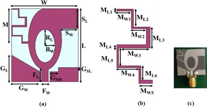
constructed antenna in an acrylonitrile butadiene styrene (ABS) casing. CONSTRUCTION OF THE THIRTY-TWO PORT DIVERSE ANTENNA UNIT CELL The proposed antenna element is constructed on Rogers
5880 substrate as shown in Fig. 1. The substrate has a thickness of 1.52 mm, dielectric constant of 2.2, and loss tangent of 0.0009. The antenna structure is of an elliptical patch connected
to a rectangular stub and asymmetric meander line. The antenna is designed using CST Microwave Studio Software. An asymmetric CPW feed supplies power to the unit cell. Figure 1(a) and (b)
show the unit cell structure and the asymmetric meander line element. An elliptical slot is introduced within the elliptical patch to increase impedance bandwidth. In the proposed antenna
element, the asymmetric meander line connects the left side of the elliptical patch, while a rectangular stub is included to the right top perspective of the patch. Figure 1(c) demonstrates
the manufactured prototype of the antenna element, and it measures 22 mm × 20 mm. Figure 2 displays the simulated and measured _S_11-parameters of the antenna element. The plot clearly shows
that the _S_11 values are lesser than −10 dB from 3 to 40 GHz. Tables 1 and 2 display the structural parameters for the element and asymmetric meander line, respectively. EVOLUTION OF THE
DEVELOPED ANTENNA ELEMENT The thirty-two port antenna development stages are demonstrated in Fig. 3, and Fig. 4 shows the respective impedance bandwidth plots. In stage I, an
elliptical-shaped patch fed by a CPW is introduced, which offers a bandwidth of 33.14 GHz (3.79 to 9.71 GHz and 12.78 to 40 GHz). When constructing a SWB antenna, it is challenging to
achieve a lower frequency range with a compact structure. In stage II, an elliptical slot measuring 5.83 mm × 3 mm is introduced to increase the bandwidth at lower frequencies. The antenna
covers frequencies ranging from 3.69 to 5.03 GHz, 7.15 to 9.9 GHz, and 12 to 40 GHz. In stage III, a rectangular stub is added, allowing the antenna to operate between 3.3 and 4.29 GHz, 7 to
9.6 GHz, and 12.63 to 40 GHz. Consequently, when compared to stage II, the 390 MHz frequency shifts to a lower frequency level. In stage IV, meander lines are introduced to increase the
bandwidth in the lower frequency range, resulting in a 330 MHz shift (3 to 4.2 GHz and 6.89 to 40 GHz) in the lower frequency range when compared to stage III. In addition, an impedance
bandwidth of 34.31 GHz is achieved, exceeding that of stages I, II, and III. In stage V, an asymmetric CPW is introduced to eliminate notching and achieve a SWB, and the antenna operates
from 3 to 40 GHz and higher, covering an impedance bandwidth of 37 GHz and more, which is larger than stages I, II, III, and IV. Thus, the SWB radiating element has evolved to provide a
bandwidth ratio greater than 10:1. An elliptical patch is considered for the proposed SWB antenna as it can provide a wider bandwidth than conventional rectangular or circular patches. It
also helps to evenly distribute current across the patch, which improves frequency response. CPW feed is used to feed the patch because it has lower radiation losses than microstrip lines,
particularly at higher frequencies. Also, CPW is simple to fabricate as both the patch and ground are in the same plane, and it can be easily integrated with other electronic circuits. An
elliptical slot is introduced as it affects current distribution and provides a wider bandwidth. A rectangular stub is introduced because it has frequency tuning capabilities. By varying the
dimensions of the stub, the resonant frequency can be shifted to achieve the desired operating frequency. The position and length of the rectangular stub play a major role in impedance
matching. The introduction of meander lines helps in tuning the antenna to a lower frequency as the electrical length increases. An asymmetric CPW is used to provide a wide bandwidth. The
asymmetry structure alters the current distribution, increasing the operational frequency range of the antenna. SURFACE CURRENT DISTRIBUTION The surface current distribution of the developed
antenna element is demonstrated in Fig. 5. The surface current distribution is observed at 3.8 GHz, 10 GHz, 20 GHz, and 40 GHz. Figure 5 shows that at 3.8 GHz, the current density is
concentrated in the lower region of the asymmetric meander lines, while at 10 GHz, the current density is denser on the right perspective of the patch and meander lines. At 20 GHz, the
current density is large in the coplanar region, while at 40 GHz, the current density is denser in the upper region of the patch. MIMO ANTENNA The designed antenna element is developed into
a thirty-two port diverse antenna, as shown in Fig. 6(a). When viewed from the front, the constructed MIMO antenna is made up of five planes: one is the base plane, two are in the direction
of X, and two are in the Y-direction. The base plane consists of eight elements, the third of which is orthogonal to the first and second. Element 5 is orthogonal to elements 3 and 4,
element 7 is orthogonal to elements 5 and 6, and element 1 is orthogonal to elements 7 and 8. The four planes in the X- and Y-directions each contain six elements. The X and Y planes are
perpendicular to the base plane, with three elements above and three elements below. There are two X planes and two Y planes, identified as X_plane_1, X_plane_2, Y_plane_1, and Y_plane_2. In
X_plane_1, element 9 is orthogonal to elements 10 and 11, and element 12 to elements 13 and 14. In the second X plane, element 15 is orthogonal to elements 16 and 17, and element 18 is
orthogonal to elements 19 and 20. In Y_plane_1, element 21 is orthogonal to elements 22 and 23, while element 24 is orthogonal to elements 25 and 26. In the second Y plane, element 27 is
orthogonal to elements 28 and 29, and element 30 is orthogonal to elements 31 and 32. The isolation between the elements must be increased for better diverse antenna performance, while the
envelope coefficient correlation (ECC) has to be reduced. To achieve good isolation, the proposed thirty-two port diverse antenna maintains 10 mm distance between each element. Figure 6(b)
demonstrates the manufactured prototype of the thirty-two port diverse antenna, and it measures 82 mm × 82 mm. RESULTS AND INFERENCES RADIATION PROPERTIES OF THE ANTENNA The developed
thirty-two port SWB diverse antenna is manufactured and examined, and its simulated and measured characteristics are discussed here. _S_-PARAMETERS OF THE ANTENNA The simulated as well as
measured reflection coefficients of the constructed single element antenna are displayed in Fig. 2. The reflection coefficients are found to be less than −10 dB from 3 to 40 GHz. Figure 7
depicts the _S__ii_ characteristics of the thirty-two port MIMO antenna. The _S__ii_ of the designed antenna are plotted in five different planes. The _S__ii_ characteristics of antenna_1 of
the base plane, antenna_9 of the X_plane_1, antenna_16 of the X_plane_2, antenna_22 of the Y_plane_1, and antenna_30 of the Y_plane_2 are plotted. Figure 7 displays that the proposed
thirty-two port SWB MIMO resonates from 3 to 40 GHz. Another factor to account for in MIMO antenna design is mutual coupling.The _S__ij_ characteristics of the developed antenna for
antenna_1 are demonstarted in Fig. 8. The mutual coupling value is found to be lower than −15 dB at all ports. The _S_-parameters of the constructed antenna are tested using a vector network
analyzer and the graphs are visualized using a laptop, as illustrated in Fig. 9. BANDWIDTH RATIO, FRACTIONAL BANDWIDTH (FBW), AND BANDWIDTH DIMENSIONAL RATIO (BDR) Bandwidth ratio is
defined as the ratio of lower to higher cut-off frequencies. A SWB antenna should have a bandwidth ratio of at least 10:1. Fractional bandwidth (FBW) refers to the difference between the
higher and lower cut-off frequencies divided by the centre frequency. The expression of the FBW is given as, $$FBW=\frac{{f}_{2}-{f}_{1}}{{f}_{c}}$$ (1) where upper cut-off frequency is
represented as _f_2, _f_1 is the minimal cut-off frequency, and _f__c_ is the mid frequency. The fractional bandwidth typically ranges from 0 to 2 and is commonly represented as a percentage
between 0% and 200%. If the FBW is greater than 20%, it indicates a wideband, and for UWB, it must be greater than 50%. The bandwidth dimensional ratio (BDR) is used to verify size,
efficiency, and bandwidth of the antenna. It calculates the amount of fractional operational bandwidth allocated per electrical unit area. The expression of the BDR is given as26,
$$BDR=\frac{BW\%}{{\lambda}_{L}\times{\lambda}_{W}}$$ (2) where \({\lambda}_{L}\)is the length of the antenna element (in terms of wavelength), \({\lambda}_{W}\) is the width of the antenna
element (in terms of wavelength), and _BW_ is the bandwidth. The BDR for the designed unit cell of the thirty-two port SWB antenna is 3911. If the BDR value is high, it will cover a wide
range while remaining compact in size. The proposed unit cell has been simulated up to 100 GHz, and the impedance bandwidth is found to be lower than −10 dB from 3 to 100 GHz, resulting in
BDR and FBW greater than 33:33:1 and 189.45%, respectively. However, the developed antenna is limited to 40 GHz because of the computational time and measurement facilities constraints. The
obtained BDR and FBW of the developed MIMO antenna are 13:33:1 and 172.09%, respectively. RADIATION PATTERNS Figure 10 depicts the simulated and measured co- and cross-polarization of
suggested antenna_1 in the E- and H-planes at spectral bands of 3.8 GHz, 5.4 GHz, 6.1 GHz, 10.1 GHz, 17.5 GHz, and 20.5 GHz, while Fig. 11 depicts the radiation distribution of antenna_2.
The co- and cross-polarization of the designed antenna are tested in an anechoic chamber, as shown in Fig. 12(a) and (b). The developed antenna is used as the receiver antenna, while the
traditional horn antenna serves as the transmitter. Each element of the antenna radiates a unique radiation distribution, and the loss of gain of one element is compensated for by the other
elements. The gain characteristics and efficiency of the antenna are displayed in Fig. 13. The constructed antenna has a maximum gain of 12.5 dBi at 40 GHz. The gain obtained is above 3.9
dBi across the entire operating frequency range (3 to 40 GHz). The maximum efficiency of the constructed antenna is 94%. MIMO CHARACTERISTICS This section examines the diverse properties of
the suggested antenna, including ECC, total active reflection coefficient (TARC), diversity gain (DG), mean effective gain (MEG), and channel capacity loss (CCL). ECC can be defined as the
degree of isolation amidst dual elements of a diverse antenna. The antenna’s ECC must be zero ideally, but in real time scenarios, it should be minimal than 0.5. The ECC calculation involves
using the _S_-parameter and the far-field as17,
$$ECC\left({\rho}_{e}\right)=\frac{{|{S}_{ii}^{*}{S}_{ij}+{S}_{ji}^{*}{S}_{jj}|}^{2}}{\left(1-{\left|{S}_{ii}\right|}^{2}-{\left|{S}_{ij}\right|}^{2}\right)\left(1-{{|S}_{ji}|}^{2}-{{|S}_{ii}|}^{2}\right)}$$
(3)
$$ECC{(\rho}_{e})=\frac{{\left|\iint\left[{\overrightarrow{F}}_{1}\left(\theta,\left.\phi\right).{\overrightarrow{F}}_{2}\left(\theta,\phi\right)]d\varOmega\right.\right.\right.|}^{2}}{\iint{\left|{\overrightarrow{F}}_{1}\left(\theta,\phi\right)\right|}^{2}d\varOmega\iint{\left|\overrightarrow{{F}_{2}}\left(\theta,\phi\right)\right|}^{2}d\varOmega}$$
(4) where _S__ii_ represents the _S_-parameters of the antenna, _S__ij_ indicates the correlation of _S_-parameters of two different antenna elements, and these elements radiated field is
represented by _F_, _θ_ represents elevation angle, azimuth angle is given by _φ_, and solid angle is denoted by _Ω_. Figure 14 shows that the obtained ECC values are well below 0.1, which
is the practical limit, and thus the antenna’s performance will not be affected. The DG reduces transmission power while maintaining performance and increases the signal-to-interference
ratio. A diverse antenna’s DG value ought to be higher than 8.86 dB in practical cases. Both the far-field and the _S_-parameter can be used to determine the DG. The DG can be expressed as,
$$DG=10\sqrt{1-{\left|{\rho}_{e}\right|}^{2}}$$ (5) The obtained DG of the proposed MIMO antenna is plotted in Fig. 15. In the majority of cases, the DG is equal to 10 dB, and the attained
DG values exceed 9.9 dB. The graph clearly shows that the attained DG is within the desired limit. MEG is defined as as the capability of the antenna to acquire transmitted electromagnetic
waves. It is computed in far-field, and its practical limit is less than 3 dB. MEG can be expressed mathematically using Eq. (6).
$$MEG=\int_{0}^{2\pi}\int_{0}^{\pi}{\left[\frac{XPR}{1+XPR}{G}_{\theta}\left(\theta,\varPhi\right){P}_{\theta}\left(\theta,\varPhi\right)+\frac{1}{1+XPR}{G}_{\varPhi}\left(\theta,\varPhi\right){P}_{\varPhi}\left(\theta,\varPhi\right)\right]{\sin}\,
\theta d\theta d\varPhi}$$ (6) Table 3 shows the MEG for the developed antenna with respect to port-1. Table 3 shows that the MEG is below 3 dB, meeting the practical limits. The results
are validated for isotropic, outdoor, and indoor scenarios with XPR values of 0, 1, and 5, respectively. The TARC of a MIMO antenna is described as the ratio of the square root of reflected
power to the square root of incident power. The incident signal is denoted by _a__i_, while the reflected signal is represented by _b__i_. The TARC must be minimal than −10 dB. The smaller
the TARC, the lower the mutual coupling, and higher the isolation. Therefore, the obtained TARC value should be low, and thus the isolation increases. Figure 16 shows that the obtained TARC
is minimal than −10 dB. $$TARC=\frac{\sqrt{{\sum}_{i=1}^{N}{\left|{b}_{i}\right|}^{2}}}{\sqrt{{\sum}_{i=1}^{N}{\left|{a}_{i}\right|}^{2}}}$$ (7) The capacity loss caused by correlation in
MIMO channels is investigated using CCL, which is calculated as, $$CCL=-{{\log}}_{2}\left|{\psi}^{R}\right|$$ (8)
$${\psi}^{R}=\left[\begin{array}{cc}{\rho}_{ii}&{\rho}_{ij}\\{\rho}_{ji}&{\rho}_{jj}\end{array}\right]$$ (9) where
\({\rho}_{ii}=\left(1-{\left|{S}_{ii}\right|}^{2}-{\left|{S}_{ij}\right|}^{2}\right),{\rho}_{22}=\left(1-{\left|{S}_{jj}\right|}^{2}-{\left|{S}_{ji}\right|}^{2}\right),\)
and\({\rho}_{ij}=-\left({S}_{ii}^{*}{S}_{ij}+{S}_{ji}^{*}{S}_{ij}\right)\; {\text{and}}\; {\rho}_{ji}=-\left({S}_{jj}^{*}{S}_{ji}+{S}_{ij}^{*}{S}_{ji}\right).\) CCL of the diverse antenna
should be lower than 0.4 bits/s/Hz. Figure 17 shows that the CCL of the designed antenna is below 0.2 bits/s/Hz. Path loss analysis examines the signal propagation or attenuation that occur
between the transmitting and receiving antennas, taking into account the received signal strength and the corresponding path loss. The path loss is computed for the constructed antenna
resonating at of 5.5 GHz and 28 GHz. The separation between the transmitting and receiving antennas is varied up to 50 m, and the resulting path loss is computed. The transmitting gain of
the antenna is 3 dBi at both frequencies26,27. The gain of the receiver antenna is 3.95 dBi at 5.5 GHz and 7.5 dBi at 28 GHz, respectively. Equation (10) is used to calculate free space path
loss (FSPL). $$FSPL=20 {log}_{10}\left(d\right)+20 {log}_{10}\left(f\right)+20 {log}_{10}\left(\frac{4\pi}{c}\right)-{G}_{Tx}-{G}_{Rx}$$ (10) where _d_ is the separation between the
transmitting and receiving antennas, frequency is denoted as _f_, _G__Tx_ is the gain of the transmitting antenna, _G__Rx_ is the receiver antenna gain, and _c_ is the speed of the light.
Figure 18 depicts the obtained path loss in relation to the separation between the transmitting and receiving antennas. The obtained path loss is based on theoretical analysis; in real time,
there will be many obstacles and losses in the signal. The study of link budget is done to calculate the gain and loss of a signal in a system. It determines the reliability of signal
transmission over different distances. The separation between the transmitter antenna and the receiver antenna is varied to determine signal reliability. The link margin can be calculated
using Eq. (11)26. $$Link\, margin=Antenna\, power \left({A}_{P}\right)-Required\, power \left({R}_{P}\right)$$ (11) where antenna power (_A__p_) can be calculated using Eq. (12), and the
required power (_Rp_) can be computed using Eq. (13). $${A}_{P}\left(dB\right)={P}_{Tx}+{G}_{Tx}+{G}_{Rx}-{L}_{F}-{P}_{L}$$ (12)
$${R}_{p}\left(dB\right)=\frac{{E}_{b}}{{N}_{0}}+K{T}_{0}+{B}_{r}$$ (13) Here, transmission power is given by _P__Tx_, transmitter gain is represented as _G__Tx_, and gain of the receiver is
denoted as _G__Rx_, _L__F_ is the free space loss, and _P__L_ is the polarization mismatch loss. For 5 GHz and 28 GHz, the link margin is calculated using 0 dBm power as the input. At both
the frequencies the gain of the transmitter is considered as 3 dBi26,27, while the gain of the receiver antenna is 3.95 dBi at 5 GHz and 7.5 dBi at 28 GHz. It is determined that the
polarization mismatch loss is 3 dB. When compared to optimal phase shift keying (PSK), the _E__b_/_N_0 ratio is 9.6 dB. 203.93 dB/Hz is the noise power density (_N_0). _K_ is the Boltzman’s
constant, absolute zero temperature is given as _T_0, and _B__r_ is the bit rate, which is 12 Mb/s. The given bit rate is sufficient to transfer a high-quality image. _L__F_ can be expressed
using Eq. (14). $${L}_{F}=20{\log}\left(\frac{4\pi d}{\lambda}\right)$$ (14) Wavelength and distance _d_ between the transmitter and receiver affects the value of _L__F_. Figure 19 shows
the data transmission range for both frequencies. If there is minimal cable loss, the data transmission range increases significantly. At 5.5 GHz, the data transmission range is 43 m, while
at 28 GHz, the distance is 12.6 m. ANTENNA HOUSING The SWB diverse antenna is a promising candidate for indoor wireless communication5. By increasing the bandwidth, one can combine multiple
wireless technologies in one device to benefit the user. SWB antennas have a wide bandwidth, fast data transmission, lesser consumption of power, and minimal multipath fading. So, these
antennas can be used in areas with high signal penetration, such as shopping malls, industries, hospitals, universities, airports, multistory buildings, and smart homes. Deep signal
penetration is produced by channel path disruptions caused by obstacles such as doors, walls, objects, and celling15. An ABS casing is developed to test the antenna’s performance in the
aforementioned real-time environments. ABS material has a dielectric constant of 2.8, so it is less sensitive to electromagnetic waves. The used ABS casing is square-shaped and best suited
for mounting in building walls. Figure 20 depicts the ABS casing, its RPT 3-D machine for fabrication, the ABS with the fabricated thirty-two port SWB diverse antenna, and the measurement
setup with the ABS casing in anechoic chamber. The _S_11 of the proposed antenna with and without ABS casing are displayed in Fig. 21, and it is found that even with and without ABS casing,
the operating frequency is maintained between 3 and 40 GHz. Figure 22 depicts the radiation patterns of the constructed antenna with casing at 3.8 GHz, 5.4 GHz, 6.1 GHz, 10.1 GHz, 17.5 GHz,
and 20.5 GHz frequencies, and it is evident that the even with casing radiation pattern is omnidirectional. Table 4 shows the similarities and dissimilarities of the constructed thirty-two
SWB radiating antenna with existing SWB MIMO antenna designs. The table clearly shows that, * The constructed antenna has a greater number of elements packed in a compact space than existing
SWB antennas2,5,7,12,23,29,30. * The previously reported antennas typically take up more space due to their larger single element design5,7,12,23,28,30,31,32,33, compared to the proposed
antenna design. * The obtained bandwidth ratio and FBW of the presented antenna are higher than5,12,23,28,29,31,32,33. Even though the antennas in2,7 have a higher bandwidth ratio and FBW,
their single element size is larger than the unit cell dimension of the developed antenna. * The developed antenna peak gain is higher and polarization vectors compared to previously
reported antenna structures5,7,12,23,29,30,31,32. The antenna efficiency obtained is 94%, which is higher than antenna designs in the literature5,28,33. * The literature suggests that the
SWB MIMO antenna achieves greater diversity when arranged in 2-D rather than 3-D. * The impact of antenna housing on various parameters, such as MEG, CCL, TARC, and ECC, has not been
extensively studied in the literature. * The maximum antenna elements used in SWB MIMO antennas is eight, according to the literature. The proposed antenna includes the greatest antenna
elements. The polarisation vectors increase with the number of ports. Thus, the proposed antenna achieves a wider impedance bandwidth while maintaining a compact arrangement. The number of
elements placed takes up less space than other reported antennas. The achieved polarization vectors are higher, making the suggested antenna suitable for use in deep fading and large
scattering environments. The antenna housing effect demonstrates that the characteristics of the antenna is not affected even when placed inside the casing. In addition, the proposed MIMO
antenna can be used for massive MIMO technology by further increasing the number of antenna elements, thereby improving wireless network performance34,35. Massive MIMO systems can improve
overall energy efficiency by spreading power over a large number of antennas36. In the future, the filtering mechanism can be combined with the proposed multi-port MIMO antenna to eliminate
unwanted interfering frequencies from the SWB37,38. CONCLUSION In this paper, a thirty-two port SWB diverse antenna is presented. The antenna has a compact structure and has an impedance
bandwidth of 3 to 40 GHz. The MIMO elements are arranged in a 3-D orientation across five different planes, resulting in polarization diversity that improves link reliability. The obtained
gain is 12.5 dBi and efficiency is 94%. The diverse properties of the developed antenna are found to be within the practical range. The antenna housing effect demonstrates that the antenna’s
performance is unaffected even when placed inside a casing, allowing it to be used in environments with deep signal penetration. Therefore, the constructed antenna is appropriate for indoor
wireless communication. DATA AVAILABILITY The datasets used and analyzed during the current study are available from the corresponding author on reasonable request. REFERENCES * Kumar, S.
et al. Compact planar super-wideband monopole antenna with four notched bands. _Electronics_9, 1204 (2020). Article Google Scholar * Yu, C. et al. A super-wideband and high isolation MIMO
antenna system using a windmill-shaped decoupling structure. _IEEE Access_8, 115767–115777 (2020). Article Google Scholar * Xiao, N. et al. Low-frequency dual-driven Magnetoelectric
Antennas with enhanced transmission efficiency and broad bandwidth. _IEEE Antennas Wirel. Propag. Lett._22, 34–38 (2023). Article ADS Google Scholar * Wang, Q., Sihvola, A. & Qi, J.
A. Novel Procedure to hybridize the folded transmitarray and fabry–perot cavity with Low Antenna Profile and Flexible Design frequency. _IEEE Antennas Wirel. Propag. Lett._23(8), 2501–2505
(2024). Article Google Scholar * Khurshid, A., Dong, J., Ahmad, M. S. & Shi, R. Optimized super-wideband MIMO antenna with high isolation for IoT applications. _Micromachines_13, 514
(2022). Article PubMed PubMed Central Google Scholar * Chaudhary, A., Kumar & Manohar, M. A modified SWB hexagonal fractal spatial diversity antenna with high isolation using meander
line approach. _IEEE Access_10, 10238–10250 (2022). Article Google Scholar * Raheja, D. K., Binod, K., Kanaujia & Kumar, S. Low profile four-port super-wideband
multiple-input-multiple-output antenna with triple band rejection characteristics. _Int. J. RF Microw. Computer-Aided Eng._29, e21831 (2019). Article Google Scholar * Chen, J. et al.
Real-time spoofing detection method using three low-cost antennas in Satellite Navigation. _Electronics_13(6), 1134 (2024). Article Google Scholar * Balani, W., Sarvagya, M., Samasgikar,
A., Ali, T. & Kumar, P. Design and analysis of super wideband antenna for microwave applications. _Sensors_21, 477 (2021). Article ADS PubMed PubMed Central Google Scholar * Kundu,
S. & Chatterjee, A. A compact super wideband antenna with stable and improved radiation using super wideband frequency selective surface. _AEU Int. J. Electron. Commun._150, 154200
(2022). Article Google Scholar * Zha, S., Qu, Z., Zhang, J., Zheng, D. & Liu, P. A. Gain reconfigurable reflector antenna with Surface mounted field-induced Artificial magnetic
conductor for adaptive HIRF Prevention. _IEEE Trans. Antennas Propag._https://doi.org/10.1109/TAP.2024.3434371 (2024). Article Google Scholar * Bahmanzadeh, F. & Mohajeri, F. An SWB
MIMO antenna with dual band rejection and polarization diversity for ultra-wide band applications. _Iran. J. Sci. Technol. Trans. Electr. Eng._47, 411–419 (2023). Article Google Scholar *
Palanisamy, P. & Subramani, M. Design and experimental analysis of miniaturized octa-port UWB/SWB-MIMO antenna with triple-band rejection characteristics. _IETE J. Res._68, 4529–4543
(2022). Article Google Scholar * Raheja, D., Kumar, S., Kumar & Kumar, B. Compact quasi-elliptical-self-complementary four-port super-wideband MIMO antenna with dual band elimination
characteristics. _AEU Int. J. Electron. Commun._114, 153001 (2020). Article Google Scholar * Thangarasu, D., Thipparaju, R. R. & Palaniswamy, S. K. Compound reconfigurable symmetric
slotted MIMO antenna with ABS enclosure for indoor wireless applications. _AEU Int. J. Electron. Commun.__174_, 155059 (2024). Article Google Scholar * Wang, C., Wen, P., Huang, X., Chen,
K. & Xu, K. Terahertz dual-band bandpass filter based on spoof surface plasmon polaritons with wide upper stopband suppression. _Opt. Express_32(13), 22748–22758 (2024). Article ADS
Google Scholar * Kannappan, L. et al. 3-D twelve-port multi-service diversity antenna for automotive communications. _Sci. Rep._12, 403 (2022). Article ADS CAS PubMed PubMed Central
Google Scholar * Saxena, G., Jain, P. & Awasthi, Y. K. High diversity gain super-wideband single band-notch MIMO antenna for multiple wireless applications. _IET Microw. Antennas
Propag._14, 109–119 (2020). Article Google Scholar * Raheja, D. K. et al. Truncated elliptical self-complementary antenna with Quad-Band notches for SWB MIMO systems. _AEU Int. J.
Electron. Commun._131, 153608 (2021). Article Google Scholar * Elhabchi, M., Srifi, M. N. & Touahni, R. A novel modified U-shaped microstrip antenna for super wide band (SWB)
applications. _Analog Integr. Circuits Signal Process._102, 571–578 (2020). Article Google Scholar * Ramanujam, P., Venkatesan, P. G. R., Arumugam, C. & Ponnusamy, M. Design of
miniaturized super wideband printed monopole antenna operating from 0.7 to 18.5 GHz. _AEU Int. J. Electron. Commun._123, 153273 (2020). Article Google Scholar * Kumar, P., Urooj, S. &
Alrowais, F. Design of quad-port MIMO/Diversity antenna with triple-band elimination characteristics for super-wideband applications. _Sensors_20, 624 (2020). Article ADS PubMed PubMed
Central Google Scholar * Ahmed, B. T., Carreras, D. C. & Marin, E. G. Design and implementation of super wide band triple band-notched MIMO antennas. _Wirel. Pers. Commun._121,
2757–2778 (2021). Article Google Scholar * Kumar, S., Raheja, D. K., Palaniswamy, S. K. & Kanaujia, B. K. Hala Mostafa, Hyun Chul Choi, and Kang Wook Kim. Design and implementation of
a Planar MIMO Antenna for Spectrum-sensing applications. _Electronics_12, 3311 (2023). Article Google Scholar * Kundu, S. A Compact super wideband planar monopole Antenna for microwave
imaging applications. _Natl. Acad. Sci. Lett._46, 337–341 (2023). Article Google Scholar * Govindan, T., Palaniswamy, S. K., Kanagasabai, M., Kumar, S. Agarwal, R., Kumar, R. &
Panigrahy, D. Design and analysis of a conformal MIMO ingestible Bolus Sensor Antenna for Wireless Capsule Endoscopy for Animal Husbandry. _IEEE Sens. J._ (2023). * Xia, A. et al. and. 28
GHz MIMO channel capacity analysis for 5G wireless communication systems. In _2018 12th International Symposium on Antennas, Propagation and EM Theory (ISAPE)_, 1–4. IEEE (2018). *
Srivastava, K. et al. Compact eight-port MIMO/diversity antenna with band rejection characteristics. _Int. J. RF Microw. Comput. Aided Eng._30, e22170 (2020). Article Google Scholar *
Gotra, S., Varshney, G., Pandey, V. S. & Yaduvanshi, R. S. Super-wideband multi-input–multi-output dielectric resonator antenna. _IET Microw. Antennas Propag._14, 21–27 (2020). Article
Google Scholar * Oni, M. A., Islam, S. H., Shehab, S., Hassan & Dey, S. Design and analysis of a low-profile, elliptical patch Super Wide Band (SWB) MIMO antenna. In _2015 International
Conference on Advances in Electrical Engineering (ICAEE_), 117–120. IEEE (2015). * Esmail, B. A. F. et al. Design of compact dual-port super wideband MIMO antennas for communication
systems. In _2021 IEEE Asia-Pacific Conference on Applied Electromagnetics (APACE)_, 1–4. IEEE (2021). * Rahman, M., Al-Bawri, S. S., Abdulkawi, W. M., Aljaloud, K. & Islam, M. T. A
unique SWB multi-slotted four-port highly isolated MIMO antenna loaded with metasurface for IOT applications-based machine learning verification. _Eng. Sci. Technol. Int. J._50, 101616
(2024). Google Scholar * Aliqab, K., Armghan, A., Alsharari, M. & Aly, M. H. Highly decoupled and high gain conformal two-port MIMO antenna for V2X communications. _Alex. Eng. J._74,
599–610 (2023). Article Google Scholar * Zhang, R. et al. Integrated Sensing and Communication with massive MIMO: A unified tensor approach for channel and target parameter estimation.
_IEEE Trans. Wirel. Commun._https://doi.org/10.1109/TWC.2024.3351856 (2024). Article Google Scholar * Wen, C. et al. FDA-MIMO technique with application to STAP Radar. _IEEE Trans. Aerosp.
Electron. Syst._58(1), 74–95 (2022). Article ADS Google Scholar * Huang, D. et al. A spatial–temporal integrated framework for end-to-end micro-UAV trajectory tracking and prediction
with 4-D MIMO radar. _IEEE Internet Things J._10(21), 18821–18836 (2023). Article Google Scholar * Wen, P. et al. Synthesis design of high-selectivity wideband balanced bandpass filter
based on parallel coupled lines. _AEU Int. J. Electron. Commun._176, 155159 (2024). Article Google Scholar * Wen, P., Jiang, Y., Liu, F., Ma, Z. & Wang, Y. Direct synthesis of
continuously tunable Wideband Bandpass Filtering Attenuator with multiple transmission Zeros. _IEEE Trans. Circuits Syst. II Express Briefs_. https://doi.org/10.1109/TCSII.2024.3386034
(2024). Article Google Scholar Download references ACKNOWLEDGEMENTS This research was supported in part by the National Research and Development Program through the National Research
Foundation of Korea (NRF) funded by the Ministry of Science and ICT (No. RS-2023-00281275), and in part by the BK21 FOUR project funded by the Ministry of Education (No. 4199990113966).
AUTHOR INFORMATION AUTHORS AND AFFILIATIONS * Department of Electronics and Communication Engineering, Faculty of Engineering and Technology, SRM Institute of Science and Technology,
Kattankulathur, 603203, India Annal Joy J & Sandeep Kumar Palaniswamy * Department of Electronics and Communication Engineering, Galgotias College of Engineering and Technology, Greater
Noida, 201310, India Sachin Kumar * Department of Electronics and Communication Engineering, College of Engineering, Guindy, Anna University, Chennai, 600025, India Malathi Kanagasabai *
School of Electronic and Electrical Engineering, Kyungpook National University, Daegu, 41566, Republic of Korea Hyun Chul Choi & Kang Wook Kim Authors * Annal Joy J View author
publications You can also search for this author inPubMed Google Scholar * Sandeep Kumar Palaniswamy View author publications You can also search for this author inPubMed Google Scholar *
Sachin Kumar View author publications You can also search for this author inPubMed Google Scholar * Malathi Kanagasabai View author publications You can also search for this author inPubMed
Google Scholar * Hyun Chul Choi View author publications You can also search for this author inPubMed Google Scholar * Kang Wook Kim View author publications You can also search for this
author inPubMed Google Scholar CONTRIBUTIONS A.J.J., S.K.P. and S.K. conceived and performed simulations, experiment, and drafted the manuscript. M.K., H.C.C. and K.W.K. conducted the
experiment and analyzed the results. S.K.P. and K.W.K. supervised the overall work and provided funding for the experiments. All authors reviewed the manuscript. CORRESPONDING AUTHORS
Correspondence to Sandeep Kumar Palaniswamy or Kang Wook Kim. ETHICS DECLARATIONS COMPETING INTERESTS The authors declare no competing interests. ADDITIONAL INFORMATION PUBLISHER’S NOTE
Springer Nature remains neutral with regard to jurisdictional claims in published maps and institutional affiliations. RIGHTS AND PERMISSIONS OPEN ACCESS This article is licensed under a
Creative Commons Attribution 4.0 International License, which permits use, sharing, adaptation, distribution and reproduction in any medium or format, as long as you give appropriate credit
to the original author(s) and the source, provide a link to the Creative Commons licence, and indicate if changes were made. The images or other third party material in this article are
included in the article’s Creative Commons licence, unless indicated otherwise in a credit line to the material. If material is not included in the article’s Creative Commons licence and
your intended use is not permitted by statutory regulation or exceeds the permitted use, you will need to obtain permission directly from the copyright holder. To view a copy of this
licence, visit http://creativecommons.org/licenses/by/4.0/. Reprints and permissions ABOUT THIS ARTICLE CITE THIS ARTICLE Joy J, A., Palaniswamy, S.K., Kumar, S. _et al._ Thirty two port
super wideband diversity antenna for indoor communications. _Sci Rep_ 14, 25104 (2024). https://doi.org/10.1038/s41598-024-76008-6 Download citation * Received: 13 June 2024 * Accepted: 09
October 2024 * Published: 23 October 2024 * DOI: https://doi.org/10.1038/s41598-024-76008-6 SHARE THIS ARTICLE Anyone you share the following link with will be able to read this content: Get
shareable link Sorry, a shareable link is not currently available for this article. Copy to clipboard Provided by the Springer Nature SharedIt content-sharing initiative