- Select a language for the TTS:
- UK English Female
- UK English Male
- US English Female
- US English Male
- Australian Female
- Australian Male
- Language selected: (auto detect) - EN
Play all audios:
ABSTRACT In order to improve the efficiency of the self-priming pump in the outdoor emergency rescue mobile pump truck, this paper took the key energy conversion component-impeller as the
target and used the orthogonal experimental design method to optimize its hydraulic performance. Firstly the numerical calculations were compared with the experimental results to confirm the
reliability of the calculation method. Then, _L_9 (34) orthogonal design was applied to investigate the influence of the impeller diameter, the blade outlet width, the blade wrap angle and
the number of blades on the hydraulic performance of the self-priming pump. Through range analysis, the order of influence of each influencing factor on the head and efficiency of the
self-priming pump was determined, and finally obtained the optimal parameter combination scheme. The results show that the optimized self-priming pump exceeds the head of the prototype pump
at all flow conditions, and the efficiency curve at high flow conditions is significantly improved and has a wide high efficiency zone. SIMILAR CONTENT BEING VIEWED BY OTHERS NUMERICAL
SIMULATION OF THE EFFECT OF INSTALLATION HEIGHT ON SELF-PRIMING PERFORMANCE OF A PROTOTYPE SELF-PRIMING PUMP Article Open access 13 May 2025 OPTIMIZATION DESIGN OF HUMP PHENOMENON OF LOW
SPECIFIC SPEED CENTRIFUGAL PUMP BASED ON CFD AND ORTHOGONAL TEST Article Open access 15 July 2022 FLUID-STRUCTURE COUPLING CALCULATION OF A PROTOTYPE SELF-PRIMING PUMP-VEHICLE SYSTEM Article
Open access 06 May 2025 INTRODUCTION As a special kind of centrifugal pump, the self-priming pump contains obvious shape features such as gas–liquid separation chamber and return hole. In
comparison with ordinary centrifugal pumps, the self-priming function of self-priming pumps makes them widely used in flooding, irrigation and chemical industry. In recent years, many
scholars at home and abroad have conducted in-depth research on the relationship between the geometric parameters of self-priming pumps and their performance. Luo et al.1 combined orthogonal
experimental methods and gray correlation method to investigate the influence of structural parameters such as blade thickness, impeller inlet and outlet angles, the wrap angle and splitter
blade diameter on the hydraulic performance of the centrifugal pump. Through data analysis, the optimal combination of parameters for the corresponding evaluation indexes was derived. Chang
et al.2,3 established a new model for predicting self-priming performance, and analyzed the influence of nozzle geometric parameters on the performance of jet self-priming pump using
orthogonal experimental method and grey correlation method. They also achieved to improve the self-priming performance by changing the nozzle geometry, and finally tested the pump with
optimal parameters at different self-priming heights to verify its reliability. Zhang et al.4 proposed a multiobjective optimization design based on the combination of numerical simulation
technology and orthogonal experiments. The number of blades, the blade setting angle, the hub ratio, and the distance between the blade and the guide vane were identified as influencing
factors in the orthogonal test scheme. The head, efficiency, shaft power and pressure pulsation were identified as quality indicators. The simulation results showed that the final optimized
solution had significant improvements in all quality indicators compared to the prototype pump. Based on the orthogonal design principle, Wang et al.5 explored the influence of blade groove
structure on centrifugal pump performance by replacing the experimental process with numerical simulation calculations. The results showed that the slot width and slot depth are the main
influencing factors on the hydraulic performance of the pump under low flow conditions. And the effect of slotting position on hydraulic performance under high flow conditions is obvious. Li
et al.6 also took advantage of numerical simulation techniques to replace the real experimental process. Based on the principle of orthogonal design, the blade outlet width, the blade
outlet angle and the blade wrap angle were selected as influencing factors to optimize the hydraulic performance of high specific speed centrifugal pumps, while also taking into account the
anti-cavitation performance of the centrifugal pump. The numerical simulation results showed that under high flow conditions, the optimized centrifugal pump performance has a more
significant improvement. Hou et al.7 proposed a performance optimization scheme for centrifugal pumps based on local entropy generation theory and combined with orthogonal experimental
method. They selected blade outlet setting angle, the wrap angle, volute inlet width, and throat area as the influencing factors to establish the orthogonal scheme. After determining the
optimal combination of parameters, the numerical results showed a slight increase in pump efficiency and a significant reduction in entropy production. With the combination of experiments
and numerical simulations, Ding et al.8 explored the effect of variation of blade outlet angle on the internal flow field and hydraulic performance of a high specific speed centrifugal pump.
According to the comprehensive analysis, the blade outlet angle had more significant effect on pump efficiency and less effect on pump head. Under high flow conditions, increasing the blade
outlet angle significantly increased the hydraulic loss of the impeller, resulting in lower efficiency. Yousefi et al.9 addressed the issue of significant performance degradation of
centrifugal pumps when transporting oil media. The effect of geometric features such as impeller inlet and outlet angles and the blade edge shape on its performance was investigated by
numerical simulation. The simulation results showed that it operates better when the blade outlet angle increased in a certain range. When conveying thick oil media, an oval shape at the
blade inlet with an angle of 45° and a rounded outlet with an angle of 40° was the best combination of parameters for performance. Ayremlouzadeh et al.10 used Taguchi optimization method to
improve the performance of a low specific speed centrifugal pump. The results showed that the blade outlet width and blade outlet angle were important factors in enhancing shaft power and
efficiency, especially the blade outlet width. And the parameter combinations with minimum power and maximum efficiency were determined by combining with ANOVA, respectively. Elyamin et
al.11 focused on the effect of the blade number on the hydraulic performance of centrifugal pumps by means of numerical calculations. The results showed that the low blade number would lead
to poorer flow stability and increased mixing losses at the impeller outlet. In contrast, too many blades led to a weaker tendency of energy stratification, which was more likely to generate
wake and increased friction losses. By the combination of experiments and numerical simulations, Namazizadeh et al.12 optimized the overall performance of centrifugal pump by adding
different geometries of splitter blades to the impeller. Then they employed the Design of Experiment (DOE) technique and response surface methodology to obtain the optimal geometry, which
led to improvements in head and efficiency. Gao et al.13 used a four-factor three-level orthogonal experimental design method to optimize the geometric parameters of an open vortex pump, and
verified the optimization by experiments. After analyzing the data from the experiments and numerical simulations, the primary and secondary factors affecting the hydraulic performance of
the vortex pump were identified. The efficiency and head of the optimized model were improved compared to the prototype pump. In addition, it was found that due to the open impeller
structure of the vortex pump, the length of the rotating recirculation generated in the impeller would gradually decrease as the flow rate increased. Zhao et al.14 conducted a
multi-objective orthogonal optimization design of a tubular pump while maintaining low shaft power. After using a combination of range analysis and weighted matrix method, the optimal
combination of geometric parameters such as the number of blades, airfoil type, blade thickness and guide blade spacing was found. The optimized tubular pump had a wide high-efficiency
range. Pei et al.15 improved the cavitation performance of centrifugal pumps based on an orthogonal test method. By combining the results of numerical simulations and experiments, it was
concluded that the impeller inlet diameter had the greatest effect on the cavitation performance of the pump. After optimization, the cavitation performance was significantly improved with a
smaller decrease in pump efficiency and the fluid could enter the impeller more smoothly. In summary, the impeller is the most critical over-flow component in the pump, and the
determination of its structural parameters directly affects the performance of the pump. By using the orthogonal design method, scholars at home and abroad can scientifically and effectively
improve the performance of centrifugal pumps by changing the geometric parameters and determining the best parameter combination scheme. However, there are fewer studies on the parameter
optimization of self-priming pump impeller. Self-priming pumps have special structures such as gas–liquid separation chamber and reflux hole, which are obviously different from ordinary
centrifugal pumps. The optimization object of this article is a horizontal self-priming reinforced pump installed on a mobile pump truck for emergency rescue. It is of great significance to
improve efficiency and save energy in outdoor emergency rescue. This article is based on the principle of orthogonal design to determine the critical geometric factors and their influencing
levels. Numerical calculation method is used to replace the experimental process for research, and the optimal parameter combination scheme is ultimately determined. In the research process,
this paper considers the influence of the reflux hole, the front and rear pump chambers and the clearance of wear-ring on the hydraulic performance of the self-priming pump, which are
rarely considered in the research process of scholars6,7,8,9. In addition, the prototype pump belongs to the category of low specific speed, and fewer studies have been carried out on
parameter optimization based on the orthogonal design method for the impeller of low specific speed pumps. The research in this paper provides a reference for the hydraulic performance
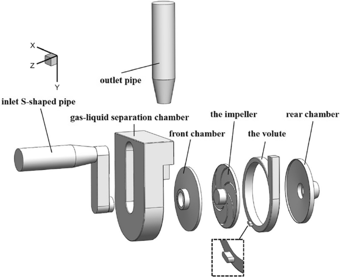
improvement of self-priming pumps. NUMERICAL CALCULATION METHOD COMPUTATIONAL MODELS AND MESH The optimization object of this paper is a DKS18-40-3 split self-priming reinforced pump, which
belongs to the category of external mixed self-priming pump, and its main design parameters are shown in Table 1. The internal flow field calculation domain model of the self-priming pump is
shown in Fig. 1. All of the calculated waters include the impeller, the volute, pump front and rear chamber, the inlet S-shaped pipe, gas–liquid separation chamber and the outlet pipe. The
water body of the return hole connects the water body of the volute with the lower part of the gas–liquid separation chamber, which is the water storage chamber of the pump. The return hole
is located at the position from the volute tongue along the direction of the impeller rotation, which is from 203.81° to 215.88°. The computational domain mesh was generated by
ANSYS19.2-ICEM. In the meshing process, local mesh refining was applied to regions where the flow field changes drastically. To facilitate meshing and reduce the errors that exist in
meshing, the front and rear pump chambers, the gap between the impeller and the volute were taken as a whole and then structured meshing was performed. In addition, due to the small
geometric features of the inlet S-shaped pipe, unstructured meshing was used to ensure a high mesh quality. The full domain mesh of the self-priming pump is shown in Fig. 2. The structured
meshes of the impeller, front and rear pump chambers, and the volute are shown in (a), (b), and (c) of Fig. 3, respectively. The number of meshes, orthogonal quality, and minimum angle for
each domain are shown in Table 2. The variation of the self-priming pump head with the mesh number under the design flow condition is shown in Fig. 4. It can be seen that as the number of
meshes increases, the calculated head tends to decrease and stabilise. When the mesh number increases to about 1.5 million, the numerical head values are basically stable with very small
fluctuations. In order to ensure the accuracy of the numerical calculation results, the impeller, the volute and other important flow components with more complex flow fields are encrypted,
and the total mesh number is finally determined to be 2001173. CONTROL EQUATIONS Zhu et al.16,17 proved that the Realizable _k–ε_ turbulence model is very suitable for pump studies, and the
numerical simulation results are in good agreement with the experimental results. Therefore, the numerical simulations in this article adopt the Reynolds-averaged Navier–Stokes (RANS) model,
with the Realizable _k–ε_ two-equation model used to close the Navier–Stokes equations. The constraint equations for the turbulent kinetic energy _k_ and the turbulent dissipation rate _ε_
in the Realizable _k–ε_ turbulence model are as follows: $$ \frac{\partial (\rho k)}{{\partial t}} + \frac{{\partial \left( {\rho ku_{j} } \right)}}{{\partial x_{j} }} = \frac{\partial
}{{\partial x_{j} }}\left[ {\left( {\mu + \frac{{\mu_{{\text{t}}} }}{{\sigma_{k} }}} \right)\frac{\partial k}{{\partial x_{j} }}} \right] + \rho \left( {P_{k} - \varepsilon } \right) $$ (1)
$$ \frac{\partial (\rho \varepsilon )}{{\partial t}} + \frac{{\partial \left( {\rho \varepsilon u_{j} } \right)}}{{\partial x_{j} }} = \frac{\partial }{{\partial x_{j} }}\left[ {\left( {\mu
+ \frac{{\mu_{{\text{t}}} }}{{\sigma_{\varepsilon } }}} \right)\frac{\partial \varepsilon }{{\partial x_{j} }}} \right] + \rho C_{1} E\varepsilon - \rho C_{2} \frac{{\varepsilon^{2} }}{{k +
\sqrt {v\varepsilon } }} $$ (2) where the coefficient \(C_{1} = \max \left( {0.43,\frac{\eta }{\eta + 5}} \right)\), coefficient of eddy viscosity \(C_{\mu } = \frac{1}{{A_{0} + A_{s} U^{*}
k/\varepsilon }}\). In the equation for the turbulent turbulent eddy viscosity coefficient, \(A_{s} = \sqrt 6 \cos \phi\), \(\phi = \frac{1}{3}\cos^{ - 1} (\sqrt 6 W)\), \(W = \frac{{E_{ij}
E_{jk} E_{ki} }}{{\left( {E_{ij} E_{ij} } \right)^{\frac{1}{2}} }}\), \(U^{*} = \sqrt {E_{ij} E_{ij} + \tilde{\Omega }_{ij} \tilde{\Omega }_{ij} }\), \(\tilde{\Omega }_{ij} = \Omega_{ij} -
2\varepsilon_{ijk} \omega_{k}\), \(\Omega_{ij} = \overline{\Omega }_{ij} - \varepsilon_{ijk} \omega_{k}\). The constant values in the above equation are: _σ__ε_ = 1.2, _C_2 = 1.92, _A_0 =
4.0. The time derivative is zero when calculated as a constant. NUMERICAL SOLUTION In this paper, FLUENT 19.2 is used to perform the constant numerical calculations for the hydraulic
performance of the self-priming pump. The coupling of the pressure and velocity fields is solved by the SIMPLE method. In the iterative calculation process, the convergence accuracy of
velocity components in each direction, turbulent kinetic energy _k_, and turbulent dissipation rate _ε_ are all set to the default value of 10–4, and the residuals are considered to be
converged if they are less than this standard. If the residual calculated during iterations cannot reach the standard, the convergence of the simulation can also be judged by monitoring the
stability of performance parameters. In this study, the monitored quantities are the head and impeller torque of the self-priming pump. Data is transferred between different domains through
mutual coupling of their interfaces. Among them, the movement of the impeller domain is realized by using the Multiple Reference Frame (MRF) rotation model, while the other water domains
remains in a stationary state. The default no-slip boundary condition is used at the solid wall, and the standard wall function is used to treat the near-wall surface. The velocity inlet
boundary is applied to the inlet of the self-priming pump, according to the conservation of mass and the incompressibility of the fluid, the inlet velocity is determined by the flow rate and
the inlet diameter, as shown in Eq. (3), while assuming that the tangential velocity and radial velocity of 0. The initial values of _k_ and _ε_ at the inlet can be determined by the Eq.
(4): $$ {\text{v = }}\frac{Q}{A} = \frac{4Q}{{\pi d^{2} }} $$ (3) $$ \left\{ \begin{gathered} k = \frac{3}{2}(I\overline{u} )^{2} \hfill \\ \varepsilon = C_{\mu }^{{{3 \mathord{\left/
{\vphantom {3 4}} \right. \kern-0pt} 4}}} \frac{{k^{{{3 \mathord{\left/ {\vphantom {3 2}} \right. \kern-0pt} 2}}} }}{l} \hfill \\ \end{gathered} \right. $$ (4) where, _l_ = 0.07_L_, _L_ is
the characteristic length, which in this paper takes the value of the diameter at the inlet. _I_ is the turbulence intensity, \(I \approx 0.16{\text{Re}}^{ - 1/8}\), \({\text{Re}} =
\frac{{{\overline{\text{u}}} \cdot L}}{{\text{v}}}\), and \({\overline{\text{u}}}\) is the mean velocity at the inlet. \(C_{\mu } \approx 0.09\) is the empirical constant in the turbulence
model. In this paper, the free outflow boundary condition is chosen, assuming that the flow is fully developed at the outlet of the computational domain. The velocity components
\({\text{u}}_{{{\text{out}}}}\), pressure \({\text{p}}_{{{\text{out}}}}\), turbulent kinetic energy \({\text{k}}_{{{\text{out}}}}\) and turbulent dissipation rate
\(\varepsilon_{{{\text{out}}}}\) are taken as the second type of boundary conditions, i.e. \(\frac{{\left. {\partial u_{j} } \right|_{{\text{out }}} }}{{\partial \vec{n}}} = 0\),
\(\frac{{\partial p_{{\text{out }}} }}{{\partial \vec{n}}} = 0\), \(\frac{{\partial k_{{\text{out }}} }}{{\partial \vec{n}}} = 0\), \(\frac{{\partial \varepsilon_{{\text{out }}} }}{{\partial
\vec{n}}} = 0\)\((j = 1,2,3)\). RELIABILITY VERIFICATION OF NUMERICAL METHODS The comparison between the hydraulic performance parameters of the self-priming pump under all flow conditions
based on the above numerical calculation method and the experimental results is shown in Fig. 5. It can be seen that the numerical calculation results agree well with the experimental
results. As the flow increases, both the test head and the calculated head gradually decrease. Under low and high flow conditions, the error between the test value and the calculated value
is high, and the maximum difference in head is about 0.862 m, with an error of about 2.372%. The shaft power gradually increases with the flow rate, and exhibits a similar discrepancy to the
head curve. Under low and high flow conditions, the error between the test value and the calculated value is high, and the maximum difference in shaft power is about 0.229 kW, accounting
for about 9.778% of the test value. Furthermore, the efficiency curve calculated based on numerical simulation shows good agreement with experimental results. It shows an increase followed
by a decrease, with a maximum efficiency value occurring near the design flow condition. The difference between the calculated and experimental results is within 8%. To sum up, the above
numerical calculation methods are within acceptable limits, except under low flow conditions, confirming the high reliability of the above numerical calculation method. Based on this,
subsequent numerical calculations will be carried out using this method. ORTHOGONAL DESIGN SCHEME DETERMINATION OF ORTHOGONAL DESIGN FACTORS AND LEVELS In combination with the structure of
the self-priming pump and the relevant reference6, the key factors influencing the hydraulic performance of the self-priming pump are determined to be the impeller diameter (_D_2), the blade
outlet width (_b_2), the blade wrap angle (_φ_) and the number of blades (_Z_), which are expressed as A, B, C and D respectively. The impeller diameter of the prototype pump is 166 mm, the
blade outlet width is 8 mm, the blade wrap angle is 70° and the number of blades is 6. The levels of the influencing factors are determined according to the arithmetic progression rule, and
the orthogonal design factors and level table are shown in Table 3. The orthogonal design scheme used in this paper is four factors and three levels, that is, the number of levels of the
factors is 3, the number of factors is 4. Depending on the principle of orthogonality, it is determined that a total of 9 experiments need to be conducted. The corresponding orthogonal table
is denoted as _L_9 (34). About factor A, the impeller diameter of the prototype self-priming pump is 166 mm. Theoretically, the prototype data should be used as a reference to increase and
decrease the corresponding tolerance values as other levels. But considering the small height of the first section of the volute, increasing the diameter of the impeller will result in a
smaller gap between the impeller and the volute tongue, which will lead to a more obvious effect of dynamic and static interaction between the rotor and the stator. This is not conducive to
the stable operation of the pump. Therefore, reducing the tolerance of the prototype impeller size is taken as the new factor levels. ORTHOGONAL DESIGN SCHEMES AND QUALITY INDICATORS The
nine schemes based on the orthogonal Design of experiments are shown in Table 4, of which Scheme 2 is the parameter combination of the prototype pump. The quality indicators selected in this
paper are the head and efficiency. Based on the parameter combinations in Table 4, the impellers in each of the nine test schemes are modeled and structurally meshed, and the meshes are
shown in Fig. 6. ANALYSIS OF RESULTS HYDRAULIC PERFORMANCE The head and efficiency curves for various flow conditions under 9 schemes are shown in Figs. 7 and 8. It can be found that there
are obvious differences in the head curves, but the trend of the curves remains the same, i.e., the head decreases gradually with the increase of the flow rate, and the decreasing trend
becomes more obvious. The head result of Scheme 1 is the best, which is higher than other schemes in each flow condition, including the head curve of the prototype pump. Obviously, if the
head alone is the only indicator, Scheme 1 is the optimal scheme. Compared with the head curve, the impeller geometry parameters have a relatively small influence on the efficiency curve. At
low flow conditions, the difference between the efficiency curves is relatively small. At high flow rate conditions, the difference in efficiency curves between the schemes becomes more
obvious. Under the design flow conditions, the efficiency values of Scheme 1, Scheme 5 and Scheme 9 are very close, about 41.387%, 41.460% and 41.779%, respectively. And all of them are
higher than the other six groups of schemes. However, under high flow conditions, it is not satisfactory that the efficiency of Scheme 9 has a significant decrease. In comparison with Scheme
1 and Scheme 5, Scheme 5 is higher. Therefore, if the head is the only indicator, Scheme 5 is the optimal scheme. In summary, if both the head and efficiency are taken into account as
indicators, the best scheme cannot be determined. The above analysis only compares the calculated data obtained from the designed 9 schemes and can only be used for preliminary judgment. The
order of influence of each factor on the two quality indicators is now considered by range analysis. RANGE ANALYSIS Combined with the orthogonal design principle, the hydraulic performance
parameters of each scheme are analyzed for extreme differences under the design flow condition (15 m3/h). Table 5 shows the calculated results of the hydraulic performance of each scheme at
its design flow rate. In the range analysis, the sum of the test indicators (_K_), the mean of the test indicators (_k_) and the range of each quality indicator (_R_) should be calculated.
Then the influence order of each factor on the quality indicators can be determined by using the range to assess their relative importance. $$ k_{ij} = \overline{K}_{ij} =
\frac{1}{n}\sum\limits_{i}^{n} {K_{ij} } $$ (5) where _K__ij_ is the sum of the quality indicators of the _j-_th factor corresponding to level _i_, \(\overline{K}_{ij}\) is the average of
_K__ij_. And _i_, _j_ are the level number and factor number respectively, _n_ is the number of levels of the _j-_th factor. $$ R_{j} = max\left\{ {\overline{K}_{ij} } \right\} - min\left\{
{\overline{K}_{ij} } \right\}\quad \left( {i = {1},{2}, \ldots ,{\text{n}}} \right) $$ (6) where R_j_ is the range of the _j-_th factor. \(max\left\{ {\overline{K}_{ij} } \right\}\),
\(min\left\{ {\overline{K}_{ij} } \right\}\) are the maximum and minimum values of the average of the quality indicator of the _j-_th factor, respectively. Table 6 shows the range analysis
of head and efficiency. It can be seen that if the head is the only indicator, the optimal combination of parameters is A1B1C3D1, which corresponds to the impeller diameter of 166 mm, blade
outlet width of 9 mm, blade angle of 60° and the number of blades of 7. The influence order of each factor on the degree of head is: A > D > B > C, that is, the impeller diameter
> the number of blades > the blade outlet width > the blade wrap angle. Similarly, if only efficiency is the only indicator, the optimal combination of parameters is A3B2C1D1. Which
corresponds to the impeller diameter of 158 mm, the blade outlet width of 8 mm, blade angle of 80° and the number of blades of 7. The influence order of each factor on the efficiency is: A
> D > B > C, that is, the number of blades > the impeller diameter > blade exit width > the blade wrap angle. In summary, it is found that the optimal combination of head
and efficiency parameters do not all coincide, so further comprehensive analysis of the two indicators is required to select the best scheme that takes into account the optimal head and
efficiency. Figures 9 and 10 show the indicator-factor diagrams corresponding to head and efficiency respectively. It can be found that the influence factor A, the impeller diameter, has a
significant effect on the head. As the impeller diameter increases, the head gradually rises. Obviously, when the head indicator is considered alone, the larger impeller diameter is better.
However, when considering the efficiency indicator, as the impeller diameter increases, the efficiency shows a trend of first decreasing and then increasing, and obviously the smaller
impeller diameter is better. Combining the two quality indicators, when the impeller diameters are 158 mm and 166 mm, the corresponding efficiency indicator values are 40.971% and 40.714%
respectively, with a small difference. But the values of the head indicator are 28.42 m and 31.85 m respectively, with a difference of 3.43 m. Under comprehensive analysis, the optimal value
of the impeller diameter should be 166 mm, i.e. A1 level. For the factor B, the blade outlet width, it can be seen that the change in factor B has a relatively small effect on head and
efficiency, so it is a secondary factor for both quality indicators. When considering the head indicator alone, the larger blade outlet width provides a better head. When the blade outlet
width is 8 mm and 9 mm, the corresponding efficiency indicator values are 40.883% and 40.483%, respectively. The difference is only 0.4%, and the relative proportion of the difference is
0.979%. While the head indicators are 30.17 m and 30.98 m, corresponding to a difference of 0.81 m, the relative proportion of 2.625%. Under comprehensive analysis, the optimal level of the
blade outlet width should be 9 mm, i.e. B1 level. For the factor C, the blade wrap angle, it can be seen that C is also a secondary factor for both quality indicators. When the head
indicator is considered in isolation, the head decreases with increasing the blade wrap angle, with the smaller blade wrap angle providing a better head. But the efficiency indicator shows a
trend of decreasing and then increasing with the increase of the blade wrap angle. Consistent with the analysis methods of the previous two factors, when the blade wrap angle is 60° and
80°, the corresponding head indicators are 30.87 m and 29.33 m respectively. The difference is 1.54 m, and the relative percentage of the difference is 4.986%. The corresponding efficiency
indicators are 40.721% and 40.789%, with a difference of 0.068%, and the relative percentage is 0.167%. Under the comprehensive analysis, the optimal value of the blade wrap angle should be
60°, i.e. C3 level. For the factor D, the number of blades, it can be seen that the factor D is more important for the two quality indicators. Both quality indicators increase gradually with
the number of blades, so the optimal number of blades should be 7, i.e. D1 level. In summary, the optimal combination of impeller parameters should be A1B1C3D1, corresponding to the
following parameters: the impeller diameter of 166 mm, the blade outlet width of 9 mm, the blade wrap angle of 60° and the number of blades of 7. However, this combination of parameters is
not included in the initial orthogonal experimental design of nine schemes, so it is necessary to calculate the hydraulic performance of the self-priming pump for the A1B1C3D1 parameter
combination. RESULT VALIDATION According to the analysis of the factor indicators table in the orthogonal design, the optimal parameter combination A1B1C3D1 is derived. The impeller of the
optimal parameter combination is modelled and structurally meshed, and its impeller mesh is shown in Fig. 11. The numerical calculation data of the self-priming pump with this impeller is
shown in Table 7. After the range analysis, the optimal parameters combination is determined to be Scheme 10, and its performance curves are compared in Figs. 12 and 13. It is easy to see
that the numerical simulation results for Scheme 10 are all improved to some extent compared to the 9 schemes in the orthogonal experimental design. Figure 12 shows that the head of the pump
with the optimal parameter combination is higher than the other 9 schemes, including the prototype pump, under all flow rate operating conditions. At low flow conditions, the difference is
small, while it is more obvious at high flow conditions. At the design flow rate _Q_ = 15 m3/h, the head of Scheme 10 reaches 34.16 m, which is already higher than the design head of 32 m,
indicating that the head indicator has met the design requirements. Figure 13 shows that the efficiency of Scheme 10 is not optimal in the low flow range, but the difference in efficiency at
the low flow conditions is very small overall. At the design flow condition, the efficiency of Scheme 10 is about 40.706%, which is slightly lower than that of the prototype pump at
40.810%. The best efficiency corresponds to Scheme 9 with the value of 41.779% and the difference of efficiency with Scheme 10 is only 1.073%, with a relative proportion of 2.568%. In
addition, Scheme 10 has a clear advantage in terms of efficiency in the high flow range, and it also has a wide range of high efficiency zones. In summary, Scheme 10 is more effective for
raising the head. Under the small flow conditions, the reduction in efficiency is very small. But under the high flow conditions, the high efficiency zone is wider and has obvious
advantages. Meanwhile, combined with the range analysis method, the optimal scheme can be determined as Scheme 10, with the specific parameters combination of A1B1C3D1, which corresponds to
the impeller diameter of 166 mm, the blade outlet width of 9 mm, the blade wrap angle of 60°, and 7 blades. Through analysis of the simulation results, it is demonstrated that the
optimization design of impellers based on orthogonal design principles and numerical simulation techniques has a certain guiding significance and can effectively reduce the cost and time of
experimentation. DISCUSSION This paper is based on the orthogonal design principle and combines numerical calculations to optimise the design of the impeller, the core over-flow component of
the self-priming pump. In the research process, this paper comprehensively considered the reflux hole, the front and rear pump chambers and the clearance of wear-ring on the hydraulic
performance of the low specific speed self-priming pump. The design and calculation results have achieved the optimization purpose, but there are still some improvements that can be made. *
(1) In the orthogonal design process, the interactions between the influencing factors are ignored. This will need to be investigated in depth in future work. * (2) In this paper, when
determining the performance of self-priming pumps, the indicator of quality chosen is the hydraulic performance of the self-priming pump. As the research object is a self-priming pump, other
parameters need to be studied in depth in future work, including self-priming height and self-priming time. CONCLUSION * (1) This paper adopts the Reynolds-averaged Navier Stokes model and
closes it with the Realizable k–ε turbulence model. The numerical calculation results have good agreement with the results of hydraulic performance experiments, verifying the accuracy of the
numerical simulation method. * (2) The order of factors for the degree of influence on the head is: _D_2 > _Z_ > _b_2 > _φ_. The order of influence of each factor on the degree of
efficiency is: _Z_ > _D_2 > _b_2 > _φ_. * (3) The optimal parameters combination is A1B1C3D1, namely _D_2 = 166 mm, _b_2 = 9 mm, _φ_ = 60° and _Z_ = 7. Under the design flow
conditions, the corresponding head is 34.16 m, the shaft power is 3.42 kW and the efficiency is 40.706%. Compared to the prototype pump, the head is increased by 2.28 m, and the improvement
in head is more significant under high flow conditions. * (4) In the final optimized case, the difference in efficiency is very small at low flow conditions compared with 9 cases, but there
is a significant enhancement in efficiency at high flow conditions, and with a wide high efficiency zone. DATA AVAILABILITY The data used to support the findings of this study are available
from the corresponding author upon request. REFERENCES * Luo, W. _et al._ Optimization of the structural parameters of a plastic centrifugal pump in the framework of a flow field analysis.
_FDMP_ 18, 789–813 (2022). Article Google Scholar * Chang, H. _et al._ Experimental optimization of self-priming pump based on the full factor test. _Mechanics_ 27(5), 429–434 (2021).
Article Google Scholar * Chang, H. _et al._ Experimental optimization of jet self-priming centrifugal pump based on orthogonal design and grey-correlational method. _J. Therm. Sci._ 29,
241–250 (2020). Article Google Scholar * Zhang, Y. _et al._ Multiobjective optimization design and experimental investigation on the axial flow pump with orthogonal test approach.
_Complexity_ 2019, 1–14 (2019). Google Scholar * Wang, H. _et al._ Effects of the impeller blade with a slot structure on the centrifugal pump performance. _Energies_ 13(7), 1628 (2020).
Article CAS Google Scholar * Li, Z. _et al._ Performance optimization of high specific speed centrifugal pump based on orthogonal experiment design method. _Processes_ 7(10), 728 (2019).
Article CAS Google Scholar * Hou, H. _et al._ Optimal hydraulic design of an ultra-low specific speed centrifugal pump based on the local entropy production theory. _Proc. Inst. Mech.
Eng. Part A J. Power Energy_ 233(6), 715–726 (2019). Article Google Scholar * Ding, H. _et al._ The influence of blade outlet angle on the performance of centrifugal pump with high
specific speed. _Vacuum_ 159, 239–246 (2019). Article ADS CAS Google Scholar * Yousefi, H. _et al._ Numerical simulation for obtaining optimal impeller’s blade parameters of a
centrifugal pump for high-viscosity fluid pumping. _Sustain. Energy Technol. Assess._ 34, 16–26 (2019). Google Scholar * Ayremlouzadeh, H., Jafarmadar, S., Niaki, S. R. A. Investigation on
the effect of impeller design parameters on performance of a low specific speed centrifugal pump using Taguchi optimization method. _Int. J. Fluid Power_. 161–182 (2022). * Elyamin, G. R. H.
A. _et al._ Effect of impeller blades number on the performance of a centrifugal pump. _Alex. Eng. J._ 58(1), 39–48 (2019). Article Google Scholar * Namazizadeh, M. _et al._ Optimization
of the splitter blade configuration and geometry of a centrifugal pump impeller using design of experiment. _J. Appl. Fluid Mech._ 13(1), 89–101 (2020). Article Google Scholar * Gao, X.
_et al._ Optimization design and internal flow field study of open-design vortex pump. _Shock Vib._ 2021, 1–11 (2021). Google Scholar * Zhao, W. _et al._ Multiobjective optimization of a
tubular pump to improve the applicable operating head and hydraulic performance. _Proc. Inst. Mech. Eng. Part C J. Mech. Eng. Sci._ 235(9), 1555–1566 (2021). Article Google Scholar * Pei,
J. _et al._ Cavitation optimization for a centrifugal pump impeller by using orthogonal design of experiment. _Chin. J. Mech. Eng._ 30(1), 103–109 (2017). Article CAS Google Scholar *
Zhu, J. _et al._ A numerical study on flow patterns inside an electrical submersible pump (ESP) and comparison with visualization experiments. _J. Pet. Sci. Eng._ 173, 339–350 (2019).
Article CAS Google Scholar * Zhou, D., Chen, H. & Zhang, L. Investigation of pumped storage hydropower power-off transient process using 3D numerical simulation based on SP-VOF hybrid
model. _Energies_ 11(4), 1020 (2018). Article Google Scholar Download references ACKNOWLEDGEMENTS The research was financially supported by the "Pioneer" and "Leading
Goose" R&D Program of Zhejiang (Grant No. 2022C03170), Science and Technology Project of Quzhou (Grant No. 2022K98). AUTHOR INFORMATION AUTHORS AND AFFILIATIONS * College of
Mechanical Engineering and Key Laboratory of Air-Driven Equipment Technology of Zhejiang Province, Quzhou University, Quzhou, 324000, China Yu-Liang Zhang * School of Mechanical Engineering,
Hunan University of Technology, Zhuzhou, 412007, China Kai-Yuan Zhang * The Zhejiang Provincial Key Lab of Fluid Transmission Technology, Zhejiang Sci-Tech University, Hangzhou, 310018,
China Zu-Chao Zhu Authors * Yu-Liang Zhang View author publications You can also search for this author inPubMed Google Scholar * Kai-Yuan Zhang View author publications You can also search
for this author inPubMed Google Scholar * Zu-Chao Zhu View author publications You can also search for this author inPubMed Google Scholar CONTRIBUTIONS Y.-L.Z. writed the manuscrpt; K.-Y.Z.
analyzed the flow characteristics; Z.-C.Z. checked the manuscript and revised it. All authors have read and agreed to the published version of the manuscript. CORRESPONDING AUTHOR
Correspondence to Yu-Liang Zhang. ETHICS DECLARATIONS COMPETING INTERESTS The authors declare no competing interests. ADDITIONAL INFORMATION PUBLISHER'S NOTE Springer Nature remains
neutral with regard to jurisdictional claims in published maps and institutional affiliations. RIGHTS AND PERMISSIONS OPEN ACCESS This article is licensed under a Creative Commons
Attribution 4.0 International License, which permits use, sharing, adaptation, distribution and reproduction in any medium or format, as long as you give appropriate credit to the original
author(s) and the source, provide a link to the Creative Commons licence, and indicate if changes were made. The images or other third party material in this article are included in the
article's Creative Commons licence, unless indicated otherwise in a credit line to the material. If material is not included in the article's Creative Commons licence and your
intended use is not permitted by statutory regulation or exceeds the permitted use, you will need to obtain permission directly from the copyright holder. To view a copy of this licence,
visit http://creativecommons.org/licenses/by/4.0/. Reprints and permissions ABOUT THIS ARTICLE CITE THIS ARTICLE Zhang, YL., Zhang, KY. & Zhu, ZC. Optimal design of impeller for
self-priming pump based on orthogonal method. _Sci Rep_ 13, 16491 (2023). https://doi.org/10.1038/s41598-023-43663-0 Download citation * Received: 24 June 2023 * Accepted: 27 September 2023
* Published: 01 October 2023 * DOI: https://doi.org/10.1038/s41598-023-43663-0 SHARE THIS ARTICLE Anyone you share the following link with will be able to read this content: Get shareable
link Sorry, a shareable link is not currently available for this article. Copy to clipboard Provided by the Springer Nature SharedIt content-sharing initiative