- Select a language for the TTS:
- UK English Female
- UK English Male
- US English Female
- US English Male
- Australian Female
- Australian Male
- Language selected: (auto detect) - EN
Play all audios:
ABSTRACT Hyperbaric welding is used for different steels in many underwater applications as a repair welding process. A difference between wet and dry welding processes can be made. Due to
the increased ambient pressure, these processes have special features inherent in the process that influence the cooling and penetration behaviour. The positive use of these effects outside
underwater applications is currently rarely addressed in science and application. The presented work establishes these advantages on the basis of a higher strength structural steel and
characterizes the effects on the microstructure of a joined S700MC steel and on the mechanical properties of the joint. It will be shown that a hyperbaric environment can be used to orient
the weld more towards the depth of the sheet. Furthermore, it will be shown that this change leads to modified cooling, which in itself influences the mechanical properties of the weld seam.
SIMILAR CONTENT BEING VIEWED BY OTHERS CORROSION BEHAVIOR OF AUSTENITIC STAINLESS STEEL AND NICKEL-BASED WELDED JOINTS IN UNDERWATER WET WELDING Article Open access 11 May 2024 EFFECT OF
HEAT TREATMENT ATMOSPHERES ON MICROSTRUCTURE EVOLUTION AND CORROSION RESISTANCE OF 2205 DUPLEX STAINLESS STEEL WELDMENTS Article Open access 21 March 2023 STUDY ON CORROSION, HYDROGEN
PERMEATION, AND STRESS CORROSION CRACKING BEHAVIOURS OF AISI 4135 STEEL IN THE TIDAL ZONE Article Open access 05 December 2022 INTRODUCTION Welding under hyperbaric environmental conditions
has been used for many years in underwater production and repair. Due to the place of execution, under water, very complex support equipment is sometimes necessary for the execution of the
weld seam1. A distinction is made between different types of underwater welding processes, for example, welding in dry and wet environments2. The equipment for welding in a dry atmosphere
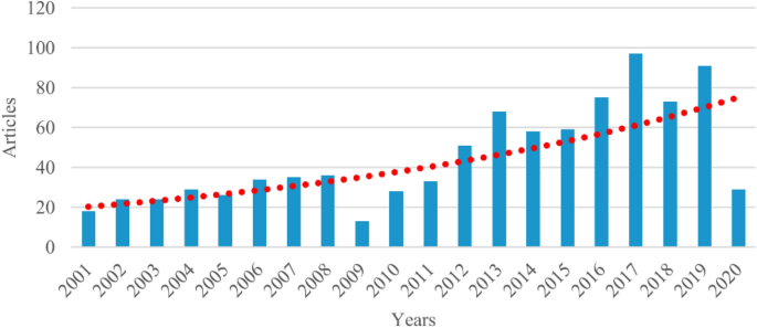
can be very complex, similar to a mini habitat for manual welding1,3. Furthermore, the research activity around underwater welding has been increasing in the last decade2, Fig. 1. The number
of published papers has increased and reached approximately 80 expected papers to be published per year in 2020. One topic in research is the process influence of the water-containing
atmosphere and the increased ambient pressure4. Furthermore, it was shown that an increased ambient pressure results in a significant reduction in the arc length at the same welding
voltage3,5,6,7,8,9. In addition to the influence on current and voltage, an influence of the increased pressure on the spatter formation could also be shown10. In the field of materials, a
clear influence of the hydrogen content on the microstructure morphology, surface roughness and crack behavior of high-strength steels, which are mostly investigated, was
shown11,12,13,14,15. Akselsen et al. showed that suitable toughness values for different pressure levels can be achieved using different types of filler metal for X70 pipeline high strength
steel16. Furthermore, they showed that the penetration depth of the weld is increased due to an increased pressure16, and they estimate some practical implications, such as filling root gaps
and a reduced layer count. They proposed a first theory for the increased penetration and focused on flow effects in the melt. The stated that the flow is directed downwards to form a
deeper penetration due to the elevated pressure. In addition, the range of materials included in the various investigations is also becoming increasingly broad. For example, the welding of
copper or aluminum alloys17 and duplex stainless steels18,19 under hyperbaric process conditions has been investigated. For aluminum alloys, a beneficial usage of hyperbaric welding in the
lower pressure ranges up to 10 bar can be assumed for the reduction of pores, a key problem regarding the welding of aluminum17. For some materials, there is a call for more investigations,
such as the welding of molybdenum alloys under hyperbaric process conditions20 and for the welding of cladded multimaterial pipelines21. However, a positive benefit in welding production due
to an increased ambient pressure has been little addressed in research, but it is of interest since a significant increase in the energy density in the arc can be realized by the arc
shortening effect and a corresponding possible voltage increase. In addition, the increased ambient pressure causes the arc to constrict and thus increases the local energy density. An
increased energy density leads to a deeper penetration of the weld seam, as Dutra showed for a modified welding process22. Bunaziv et al. showed a similar effect for welding with the CMT
mode at elevated ambient pressures5. The increase in the energy density of the arc should result in an increased welding depth and changed solidification conditions, as Azar et al.
predicted23 and Bunaziv et al. showed for a modified welding process5. The arc constriction is, in addition, dependent on the shielding gas mixture used24, as for normal GMA welds. Azar
modelled and validated the thermal cooling cycles and found an influence of the pressure on the cooling t8/5-time but classified this effect as minor25. In other studies, the effect on the
cooling time can be considered significant. An altered cooling time will lead to different mechanical properties in the weld metal and the HAZ. The work presented in this paper is intended
to shift the focus of hyperbaric welding processes away from underwater welding towards a potential improvement of conventional welding processes. For this purpose, knowledge of the
underlying relationships between the welding process boundary conditions, the ambient pressure and the geometric and mechanical weld metal and HAZ (Heat affected zone) properties is crucial.
Therefore, in the work presented hereafter, a model is derived for the dependence of the weld geometry on the set variables during hyperbaric welding. The derived statistical model will
give an overview of the relationship between the welding depths and weld metal hardness. The focus of the interpretation of the literature and the results in the discussion of the findings
will focus on a beneficial use of a hyperbaric process environment in welding without a water-containing setup. EXPERIMENTAL SETUP, MATERIALS AND METHODS To investigate the beneficial use of
hyperbaric welding in welding production, a hyperbaric chamber with an external wire feed was realized (Figs. 2 and 3). This chamber can withstand an internal pressure of up to 50 bar and
allows visual access to the joining zone. The wire electrode is fed from outside via a gate system. This eliminates the effects of the increased ambient pressure on the welding power source.
The sample movement was carried out via a separately controlled linear moving table. For the following investigations, the ambient pressure of 2 bar to 16 bar, as well as the welding
voltage and the welding current, were measured according to a statistical design of experiments in the non-synergy operation mode of the welding power source. Argon was fed into the test
chamber as a shielding gas and to top up the pressure to the desired pressure for the experiment. The chemical composition of the base material used, an S700MC low-alloyed high strength
steel, was determined by optical emission spectroscopy. Table 1 shows the results. As is usual for fine-grained structural steels, microalloys with the elements titanium, vanadium and
niobium as well as a larger proportion of manganese are present. The microstructure of S700MC is very fine-grained, ferritic and has a pronounced rolling texture (Fig. 4)26. Larger blocky
titanium nitride precipitates (yellowish) are visible throughout the whole microstructure at larger magnifications. Tensile tests were carried out to determine the quasi-static mechanical
properties of the test material (Table 2). Therefore, the rolling direction was taken into account while taking the samples26. The displayed values are the mean values for the three
specimens tested. The chemical composition of the weld filler metal was also determined by optical emission spectrometry on two-dimensional build-up welds with 4 layers and is shown in Table
3. The used welding consumable had a diameter of 1.2 mm. The statistical experimental design was set up and evaluated using Modde software (version 12.1). EXPERIMENTAL PROCEDURE AND RESULTS
The welding tests were carried out following a statistical D-optimal design of experiments (DoE), as shown in Table 4. In the D-optimal experimental design, the determinant of the
information matrix is maximized. This criterion leads to the minimization of the volume of the confidence ellipsoid for the unknown parameters of the linear regression model. Furthermore,
the DOE provides the opportunity to derive a statistical model to describe the influence of the ambient pressure on various seam characteristics. The changeable variables for the DoE are the
welding voltage for a non-synergetic welding process, the ambient pressure, and the welding current. The set point of the wire feed is given as well. Especially the welding current is
correlated to the wire feed speed. For the evaluation of the results we choose to use the welding current as setpoint rather than the wire feed speed, because the mean values of the measured
currents are corresponding with the set-point values. A significant influence of the ambient pressure on the occurring welding currents and voltages, which has been expected, has not
occurred (see section "Cooling times"). Therefore, it si possible, that in this case the welding machine will stick to current as controlled variable. The stick-out was set to 17
mm. The torch was aligned normal, without any angle, to the surface of the used substrate. Table 4 shows the results for the welding depths and hardness (HV0.2) measurements for the bead on
plate welding. The hardness measurements (HV0.2) shown in Table 4 are the mean values of the last 10 points in the weld metal of a hardness measurements line starting in the base material,
reaching at least into the middle of the weld metal. One example is shown in Fig. 5. The weld depth was determined on a cross-section as shown in Fig. 5. The welding speed was set to 30
cm/min. The welding machine used was an EWM Alpha Q 551. The wire diameter was 1.2 mm, and argon was used as the shielding gas. The derived statistical model is shown in Fig. 6 for the
relationship between ambient pressure, welding current, welding voltage and weld penetration depth. The statistical experimental design is shown in Table 4. The influence of the ambient
pressure on increasing the welding depth is visible in Fig. 6. As the pressure increases, the welding depth increases. However, the effect is not as pronounced as with the aluminum alloy
presented in17. These results are supported by findings from Xue et al. presented in27. The maximum welding depth is reached at high welding voltages and welding currents. These results and
findings from studies with aluminum17,28, a local maximum for the welding depth as a function of welding voltage and welding current, can be assumed and will form beyond the test area shown,
Fig. 7. The welding depth was measured in cross sections taken 50 mm behind the start of the weld. An example of a cross section for the measurement is shown in Fig. 8. In this case, due to
the increased ambient pressure, a more finger-shaped seam geometry in comparison to weld seams at lower pressures occurred, Fig. 8. Furthermore, the observation of the welding processes,
the high-energy welding processes with an increased ambient pressure and the finger-like shape in the cross-sections show a buried arc, as Dutra et al.22 described in their work. This buried
arc has also been seen by visual observation. A buried arc is a welding arc that can occur by welding currents above 500 A29,30. This arc burns beneath the surface of the wok piece (Fig. 6,
compare29,30,31,32). This arc also leads to a more finger-shaped bead geometry and can lead to the usage of smaller angles in weld seam preparation, which can lead to fewer layers that need
to be welded for multirun welds17. To prove this, some single runs but welds of 15 mm sheets are presented in Sect. “Butt joint” The observed effect of increased energy density in the arc,
which in extreme cases leads to a buried arc, in combination with the theory of Akselsen et al.16 that the molten pool flow is shaped to produce a deeper penetration should explain the
effects described here and in the literature. Baba et al. showed that a buried arc can significantly reduce the number of welding passes required30. Due to the constriction of the arc by the
increased pressure, the buried arc can also occur at currents below 500 A. The typical downward extended form of the buried arc already occurs at 350 A and a pressure of 8 bar, Fig. 8b.
Figure 9 shows a direct comparison between two weld seams using the same welding voltage and welding current and the same welding speed at different ambient pressures (2 bar and 16 bar). The
weld seam under 2 bar is significantly wider than that at 16 bar. On the other hand, the beginning of a finger-shaped weld seam over the entire weld seam width can also be seen at 200 A. As
shown in Fig. 9, this finger-shaped feature becomes deeper with increasing welding current. These results show the same tendencies as the literature. In particular, the results of Bunaziv
et al. show a significantly increased penetration at elevated pressure5. Due to the greater welding depth, shown in Fig. 8, and the occurrence of the buried arc effect, the observation with
the high-speed camera leads to inconclusive, nearly black-only pictures. Therefore, the buried arc cannot be presented. In the case of a buried arc, the welding arc burns beneath the base
material surface within the material, as shown in Fig. 10. WELD METAL MICROSTRUCTURE The weld seams show a microstructure of acicular ferrite typical for the filler metal used. In addition,
grain boundary ferrite is formed for higher joining energy levels. The found microstructure is typical for this type of filler metal26,33. For lower energy levels, a slight decrease in grain
size can be anticipated, which is also a typical phenomenon for this type of filler. However, a quantitative determination of the grain size of weld seams remains inconclusive. Figure 11
shows the cross section of two low-energy welds under different ambient pressures. In the lower half of the figure, the microstructure of the weld metal can be seen. In both figures,
aciucular ferrite can be observed within the former austenite grain boundaries. Furthermore, portions of proeutectoid ferrite are present. Azar et al. predicted a change in the
microstructure for higher welding energy and increased ambient pressure23. This is supported by the results. The differences in the microstructure due to different cooling show up for higher
energy welding processes, Fig. 11. In this case, in addition to acicular ferrite (AF), grain boundary ferrite (GBF) occurs at low ambient pressure. For the changed cooling due to a higher
ambient pressure, the grain boundary ferrite shows a microstructure that indicates faster cooling. This indicates a needle-like bainitic microstructure in the grain boundary ferrite. This is
supported by the SEM images of the weld metal centre Fig. 11. Within the grain boundary ferrite, cementite lamellae are increasingly visible. In summary, it can be said that the
microstructure is typical for this filler material and that there are hardly any quantifiable differences between the different energy levels and pressures. The results for the
characterization of the microstructure coincide with those for the hardness of the welds. To determine the hardness of the weld metal, a microhardness series (HV0.2) was placed from the base
metal into the weld metal, with 10 indentations made in the weld metal. The values given in Table 4 are the mean values of the 10 indentations in the weld metal (see Fig. 5). Figure 12
shows the contour plot of the statistical model for hardness as a function of ambient pressure, welding current and welding voltage. With increasing welding current, the hardness decreases,
as expected due to the increasing energy per unit length. In addition, Fig. 12 shows that with increasing ambient pressure, there is a slight decrease in hardness in the area of lower
welding voltages (below 33 V). At higher welding voltages (above 33 V), there is a slight increase in hardness. For higher welding voltages and higher pressures and/or current, the
occurrence of a buried arc lead to a change in the energy dissipation in the material and the welding efficiency will be enhanced. That means, that the weld seam will cool down slower and
this leads to lower hardness. If there is now buried arc at lower voltages/currents the arc efficiency well decrease due to the higher amount of gas that will take part in the energy
dissipation process. In addition, there is a range at medium welding voltages with no change in hardness due to the ambient pressure. It can be concluded from this that an increase in
ambient pressure is likely to change the cooling time. For lower welding voltages, this behaviour is supported by results from Azar et al. and Parshin et al. for higher voltages25,34. BUTT
JOINT To demonstrate the positive effects of a hyperbaric process environment for welding fabrication, bars with a sheet thickness of 15 mm made of S700MC were joined with the aid of a
backing plate also made of S700MC. To increase the possible weld depth beyond the welding depth selected in the statistical model, a Y-seam preparation with a 5 mm web and an opening angle
of 40° was selected. 35 V and 500A (wire feed of 22.3 m/min) were set as process variables. Figure 13 shows a cross-section of the achieved weld at 2 bar. The illustration also shows the
weld preparation schematically. The geometry and shape of the welds are comparable at all ambient pressures, and it can be seen that finger-shaped penetration leads to the feasibility of a
single-layer 15 mm thick MSG weld even at low ambient pressures. Argon was also used as the shielding gas for these tests. However, there are significant differences in the cooling times.
The possibility that a buried arc can contribute to a significant reduction in the number of layers during welding has been demonstrated by Baba et al., among others30. Furthermore, they
have shown that the necessary weld preparation can also be reduced. The stabilisation of the buried arc at increased pressure shown in the previous chapters demonstrates the potential of the
process for welding production, especially for use in the range below 500 A welding current. COOLING TIMES To determine the cooling times, type-K thermocouples were spotted at a distance of
3 mm to the left and right of the weld seam preparation when welding the butt joints. They were located in the middle of the weld length to be welded. Figure 14 shows the dependence of the
determined t8/5 times on the ambient pressure. Furthermore, the corresponding energy per unit length, which was determined from the average values of welding current and welding voltage,
which were also recorded, is shown in Fig. 14. The energy per unit length is not influenced by the ambient pressure. In contrast, the cooling time shows a clear influence of the ambient
pressure on the cooling time. Higher ambient pressures lead to an increase in the cooling time, which means that the weld cools down slower. This can be explained by a change in arc
efficiency. For higher ambient pressures, the constriction of the arc—which also leads to the buried arc effect—leads to an increase in the arc efficiency. Here, the core point is the change
in heat conduction conditions caused by the deeper penetration. This is consistent with the model for the hardness of the weld seam, which shows a slight softening of the weld seam
structure, indicating longer cooling times. An influence of an increased pressure on cooling times has been shown by Azar et al.25, but their cooling times are 2 s relatively fast, which is
typical for underwater applications. In this case, the shown cooling times are in the range between 10 and 20 s, which is typical for “normal” welding of this type of base material. An
influence on the arc efficiency was also proposed by Farrell for hyperbaric TIG welding of duplex stainless steels in19. SUMMARY The presented work shows that an increased ambient pressure
can lead to a deeper and more finger-like weld seam characteristic, which can be used in a non-underwater environment for a reduced angle in weld seam preparation and a reduced layer count
due to a deeper penetration of the weld. In addition, the dependency of the arc energy input due to the change in the arc efficiency has been shown, but this needs to be further
investigated. The presented results are in line with the existing literature. The possible reduction of weld seams and reduction of the weld seam preparation have been exemplarily shown for
a single seam joint of a 15 mm thick plate with a 40° Y-shaped weld seam preparation with 5 mm. Furthermore, statistical models were set up for the hardness and penetration as a function of
the process values. The derived statistical model can help to identify the needed process values of the welding process, including the ambient pressure for a targeted welding depth per
layer. By stabilising the buried arc through the increased ambient pressure, the number of welding layers required for thick-walled components can be significantly reduced. However, further
development steps are necessary for the implementation of hyperbaric welding on thick-walled components. Nevertheless, it could also be shown that the pressures required to stabilise the
buried arc are relatively low and that it should therefore be possible to implement a concept for locally increasing the pressure without a chamber. OUTLOOK In addition to the presented
investigations, the use of a mixture of 82% argon and 18% carbon dioxide as the shielding gas is planned. The determination of the influence of ambient pressure on toughness and other
mechanical properties is also pending. In this case a detailed study of the HAZs microstructure is planned as well. Furthermore, the next large step is the development of an out-of-chamber
hyperbaric welding torch to utilize the effects shown. DATA AVAILABILITY The datasets used and/or analysed during the current study are available from the corresponding author on reasonable
request. REFERENCES * Alajmi, E. F. & Alqenaei, A. A. Underwater welding techniques. _IJERA_ 7, 14–17. https://doi.org/10.9790/9622-0702031417 (2017). Article Google Scholar * Surojo,
E. _et al._ Recent developments on underwater welding of metallic material. _Procedia Struct. Integr._ 27, 14–21. https://doi.org/10.1016/j.prostr.2020.07.003 (2020). Article Google Scholar
* Ofem, U. U. Laser assisted arc welding process for dry hyperbaric deep water application, Cranfield University. * Parshin, S. G., Levchenko, A. M. & Maystro, A. S. Metallurgical
model of diffusible hydrogen and non-metallic slag inclusions in underwater wet welding of high-strength steel. _Metals_ 10, 1498. https://doi.org/10.3390/met10111498 (2020). Article CAS
Google Scholar * Bunaziv, I. _et al._ Dry hyperbaric welding of HSLA steel up to 35 bar ambient pressure with CMT arc mode. _Int. J. Adv. Manuf. Technol._ 105, 2659–2676.
https://doi.org/10.1007/s00170-019-04511-6 (2019). Article Google Scholar * Fydrych, D. & Kozak, T. Underwater welded joint properties investigation. _Adv. Mater. Sci._
https://doi.org/10.2478/v10077-009-0016-y (2009). Article Google Scholar * Gyasi, E. A. Welding processes of metals for offshore environment: underwater welding. Lappeenranta-Lahti
University of Technology LUT (2019). * Łabanowski, J., Fydrych, D. & Rogalski, G. Underwater welding: a review. _Adv. Mater. Sci._ https://doi.org/10.2478/v10077-008-0040-3 (2008).
Article Google Scholar * Tang, D., Niu, H., Xue, L. _et al._ Study on underwater hyperbaric dry GMAW welding. in _Proceedings of the 2017 7th International Conference on Manufacturing
Science and Engineering (ICMSE 2017)_. Atlantis Press, Paris, France (2017). * Li, K. _et al._ Droplet rebounded spatter in dry hyperbaric gas metal arc welding process. _Int. J. Adv. Manuf.
Technol._ 74, 693–698. https://doi.org/10.1007/s00170-014-5990-5 (2014). Article Google Scholar * Chen, H. _et al._ Insight into hydrostatic pressure effects on diffusible hydrogen
content in wet welding joints using in-situ X-ray imaging method. _Int. J. Hydrogen Energy_ 45, 10219–10226. https://doi.org/10.1016/j.ijhydene.2020.01.195 (2020). Article CAS Google
Scholar * Klett, J. _et al._ Effect of the water depth on the hydrogen content in SMAW wet welded joints. _SN Appl. Sci._ https://doi.org/10.1007/s42452-020-3066-8 (2020). Article Google
Scholar * Kong, X. _et al._ Measurement and analysis of the diffusible hydrogen in underwater wet welding joint. _MATEC Web Conf._ 39, 3004. https://doi.org/10.1051/matecconf/20163903004
(2016). Article CAS Google Scholar * Tomków, J. _et al._ Efecto del sistema de apantallamiento de la soldadura y el tiempo de almacenaje de los electrodos en el contenido de hidrógeno
difundido en el metal depositado. _REVMETAL_ 55, 140. https://doi.org/10.3989/revmetalm.140 (2019). Article CAS Google Scholar * Gheonea, M. C. _et al._ Influence of marine corrosion on
the roughness of the dry hyperbaric underwater MAG welding joints. _IOP Conf. Ser. Mater. Sci. Eng._ 968, 12009. https://doi.org/10.1088/1757-899X/968/1/012009 (2020). Article CAS Google
Scholar * Akselsen, O. M., Hårsvæ, A., Fostervoll, H. _et al._ Root bead profiles in hyperbaric GTAW of X70 pipeline. _Int. J. Offshore Polar Eng._ 16(2), S123–127 (2006). * Treutler, K.
_et al._ Beneficial use of hyperbaric process conditions for welding of aluminium and copper alloys. _Weld. World_ https://doi.org/10.1007/s40194-021-01088-1 (2021). Article Google Scholar
* Hu, Y. _et al._ Microstructure, pitting corrosion resistance and impact toughness of duplex stainless steel underwater dry hyperbaric flux-cored arc welds. _Materials (Basel)_
https://doi.org/10.3390/ma10121443 (2017). Article PubMed Central Google Scholar * Farrell, J. Hyperbaric welding of duplex stainless steel pipelines offshore, Cranfield University. *
Zhu, Q. _et al._ Research status and progress of welding technologies for molybdenum and molybdenum alloys. _Metals_ 10, 279. https://doi.org/10.3390/met10020279 (2020). Article CAS Google
Scholar * Bunaziv, I., Olden, V. & Akselsen, O. M. Metallurgical aspects in the welding of clad pipelines—a global outlook. _Appl. Sci._ 9, 3118. https://doi.org/10.3390/app9153118
(2019). Article CAS Google Scholar * Dutra, J. C. _et al._ High-performance GMAW process for deep penetration applications. _Weld. World_ 64, 999–1009.
https://doi.org/10.1007/s40194-020-00889-0 (2020). Article CAS Google Scholar * Azar, A. S., Fostervoll, H., Akselsen, O. M. Prediction of the thermal cycles in dry hyperbaric GMA welding
using partial differential heat transfer equations. in _Conference: 9th International Conference on Trends in Welding Research American Society for Metals_. * Azar, A. S., Ås, S. K. &
Akselsen, O. M. Analytical modeling of weld bead shape in dry hyperbaric GMAW using Ar-He chamber gas mixtures. _J. Mater. Eng. Perform._ 22, 673–680.
https://doi.org/10.1007/s11665-012-0331-z (2013). Article CAS Google Scholar * Azar, A. S., Akselsen, O. M., Fostervoll, H. Prediction of the thermal cycles in dry hyperbaric GMA welding
using partial differential heat transfer equations (2012). * Treutler, K. Schweißen von Leichtbaurahmenkonstruktionen: funktionale Werkstoffauswahl und Schweißzusatzwerkstoffmodifikation,
Universitätsbibliothek Der TU Clausthal (2019). * Xue, L. _et al._ Welding polarity effects on weld spatters and bead geometry of hyperbaric dry GMAW. _Chin. J. Mech. Eng._ 29, 351–356.
https://doi.org/10.3901/CJME.2015.1104.131 (2016). Article Google Scholar * Brechelt, S., Wiche, H., Treutler, K. _et al_. Hyperbares schweißen von aluminiumlegierungen. in _40.
Assistentenseminar Fügetechnik: DVS Berichte, Band: 357, 1. Auflage 2019_, vol. 357. DVS Media GmbH, Düsseldorf (2019). * Perić, M. _et al._ Numerical prediction and experimental validation
of temperature and residual stress distributions in buried-arc welded thick plates. _Int. J. Energy Res._ 43, 3590–3600. https://doi.org/10.1002/er.4506 (2019). Article Google Scholar *
Baba, H. _et al._ Single pass full penetration joining for heavy plate steel using high current GMA process. _Weld. World_ 61, 963–969. https://doi.org/10.1007/s40194-017-0464-7 (2017).
Article CAS Google Scholar * Baba, H. _et al._ Microstructure observation of high-current buried-arc welded joint. _Q. J. Japan Weld. Soc._ 38, 11s–15s.
https://doi.org/10.2207/qjjws.38.11s (2020). Article Google Scholar * Dreveck, N. W. _et al._ Influence of push and pull techniques on high-speed buried-arc GMAW process. _Soldag. Insp._
https://doi.org/10.1590/0104-9224/si25.23 (2020). Article Google Scholar * Treutler, K. & Wesling, V. Usage of Ti-surface-modified filler material to increase the joint strength of
high-strength low alloyed (HSLA) steels under different load types. _SN Appl. Sci._ https://doi.org/10.1007/s42452-020-03884-8 (2020). Article Google Scholar * Parshin, S. & Levchenko,
A. Underwater hyperbaric dry welding of high strength steel arctic oil and gas pipelines. _IOP Conf. Ser. Earth Environ. Sci._ 539, 12159. https://doi.org/10.1088/1755-1315/539/1/012159
(2020). Article Google Scholar Download references ACKNOWLEDGEMENTS The presented work was funded by the Volkswagen Foundation "Experiment!" framework. FUNDING Open Access
funding enabled and organized by Projekt DEAL. AUTHOR INFORMATION AUTHORS AND AFFILIATIONS * Clausthal Centre of Materials Technology - University of Technology Clausthal, Leibnizstr. 9,
38678, Clausthal-Zellerfeld, Germany K. Treutler & S. Brechelt * Institute of Welding and Machining - University of Technology Clausthal, Agricolastr. 2, 38678, Clausthal-Zellerfeld,
Germany H. Wiche & V. Wesling Authors * K. Treutler View author publications You can also search for this author inPubMed Google Scholar * S. Brechelt View author publications You can
also search for this author inPubMed Google Scholar * H. Wiche View author publications You can also search for this author inPubMed Google Scholar * V. Wesling View author publications You
can also search for this author inPubMed Google Scholar CONTRIBUTIONS The experimental work for this contribution was done by S.B. and K.T. supervised by V.W. and H.W. The funding accession
has been executed by H.W., V.W. and K.T. The interpretation of the obtained data has been done by K.T., V.W. and H.W. K.T. wrote the main manuscript text and K.T. and S.B. prepared the
figures. All authors reviewed the manuscript. CORRESPONDING AUTHOR Correspondence to K. Treutler. ETHICS DECLARATIONS COMPETING INTERESTS The authors declare no competing interests.
ADDITIONAL INFORMATION PUBLISHER'S NOTE Springer Nature remains neutral with regard to jurisdictional claims in published maps and institutional affiliations. RIGHTS AND PERMISSIONS
OPEN ACCESS This article is licensed under a Creative Commons Attribution 4.0 International License, which permits use, sharing, adaptation, distribution and reproduction in any medium or
format, as long as you give appropriate credit to the original author(s) and the source, provide a link to the Creative Commons licence, and indicate if changes were made. The images or
other third party material in this article are included in the article's Creative Commons licence, unless indicated otherwise in a credit line to the material. If material is not
included in the article's Creative Commons licence and your intended use is not permitted by statutory regulation or exceeds the permitted use, you will need to obtain permission
directly from the copyright holder. To view a copy of this licence, visit http://creativecommons.org/licenses/by/4.0/. Reprints and permissions ABOUT THIS ARTICLE CITE THIS ARTICLE Treutler,
K., Brechelt, S., Wiche, H. _et al._ Beneficial use of hyperbaric process conditions on the welding of high-strength low alloy steels. _Sci Rep_ 12, 12434 (2022).
https://doi.org/10.1038/s41598-022-16184-5 Download citation * Received: 08 October 2021 * Accepted: 06 July 2022 * Published: 20 July 2022 * DOI: https://doi.org/10.1038/s41598-022-16184-5
SHARE THIS ARTICLE Anyone you share the following link with will be able to read this content: Get shareable link Sorry, a shareable link is not currently available for this article. Copy to
clipboard Provided by the Springer Nature SharedIt content-sharing initiative