- Select a language for the TTS:
- UK English Female
- UK English Male
- US English Female
- US English Male
- Australian Female
- Australian Male
- Language selected: (auto detect) - EN
Play all audios:
ABSTRACT Various studies demonstrated new gaseous phase formation and oil swelling and viscosity reduction are the oil recovery mechanisms by carbonated water injection (CWI) with new
gaseous phase formation being the major recovery mechanism for live oil systems. However, none of the previous studies investigated the influences of dissolved gas content of the oil and oil
composition, on the new gaseous phase. This study attempts to provide insights on this area. Based on the results, during CWI as CO2 partitions into the oil the dissolved gas of the oil
liberates, which leads to in-situ new gaseous phase formation. The dissolved gas content of the crude oil has a direct impact on the saturation and growth rate of the new gaseous phase. The
new gaseous phase doesn’t form for oils that have an infinite capacity for dissolving CO2, such as light pure hydrocarbon components. Oils with limited capacity for dissolving CO2, such as
heavy hydrocarbon components, are responsible for the formation of the new gaseous phase. Therefore for a live crude oil, the relatively heavier fractions of oil are responsible for
triggering of the new gaseous phase and light to intermediate oil components control the further growth of the new gaseous phase. SIMILAR CONTENT BEING VIEWED BY OTHERS EXPERIMENTAL STUDY OF
ASPHALTENE DEPOSITION DURING CO2 AND FLUE GAS INJECTION EOR METHODS EMPLOYING A LONG CORE Article Open access 14 February 2024 ASSESSMENT OF HEAVY OIL RECOVERY MECHANISMS USING IN-SITU
SYNTHESIZED CEO2 NANOPARTICLES Article Open access 22 May 2024 AN EXPERIMENTAL STUDY TO MEASURE OIL RECOVERY FACTOR BY CHEMICAL AGENTS AND CARBON DIOXIDE AFTER WATERFLOODING Article Open
access 08 June 2022 INTRODUCTION Carbonated (CO2-enriched) water injection (CWI) is a water-based enhanced oil recovery (EOR) scenario in which water as the carrier fluid displaces dissolved
CO2 in the porous medium1. Since in this EOR technique CO2 is dissolved in the injected brine, CO2 does not present in the form of free gas phase which would eliminate the risk of
buoyancy-driven leakage as in the case of CO2 injection2. Furthermore, since CW-oil system has a more favorable mobility ratio than CO2-oil system, CO2 is more evenly distributed in the
reservoir during CWI than CO2 injection1. Several researchers1,3,4,5,6,7,8,9,10,11,12,13,14,15,16,17,18,19,20 showed the promising oil recovery potential of CWI. In their studies the
obtained additional oil recovery by CWI was mainly attributed to two major mechanisms, which are oil swelling1,3,4,5,6,7,8,9,10,11,12,13,14,15,16,17,18,19,20 and oil viscosity
reduction1,3,5,6,7,9,10,11,12,14,15,16,17,18,19,20. Their results1,3,4,5,6,7,8,9,10,11,12,13,14,15,16,17,18,19,20 showed that as carbonated water (CW) flows in the porous medium, it comes in
contact with the resident oil where CO2 partitions into the oleic phase. This CO2 mass transfer leads to oil swelling1,3,4,5,6,7,8,9,10,11,12,13,14,15,16,17,18,19,20 and oil viscosity
reduction1,3,5,6,7,9,10,11,12,14,15,16,17,18,19,20 and thereby, oil displacement, formation of an oil bank and additional oil recovery1,3,4,5,6,7,8,9,10,11,12,13,14,15,16,17,18,19,20.
However, model oil (n-Decane)1,3,8,9,10,13,15,16, mineral oils5,9,10,16,21,22 and dead crude oils1,4,6,7,11,12,14,17,18,19,20 were used in the majority of previous works reported in the area
of CWI. As a result, the role of the presence of dissolved gas in the live reservoir crude oil on the oil recovery mechanisms of CWI was not investigated by the previous
works1,3,4,5,6,7,8,9,10,11,12,13,14,15,16,17,18,19,20,21,22. For the first time, through an extensive series of high-pressure and high-temperature coreflood23,24,25, PVT26,
micromodel23,27,28 and slim tube26 experiments, as well as using fully CH4-saturated crude oils (live crude oils), we revealed the positive impact of the presence of associated gas in crude
oil on the performance and oil recovery mechanisms of CWI. According to our published micromodel experiments23,27,28, CO2 mass transfer from carbonated water into a fully-CH4 saturated crude
oil (live crude oil) led to the formation and growth of a gaseous phase inside the oil phase. This phenomenon was not observed for the carbonated water-dead oil system24. The results of our
PVT experiments26 performed for a system of CW and a fully CH4-saturated crude oil to a limited extent revealed the characteristics of the new gaseous phase. We found that as soon as CW
front comes in contact with the fully CH4-saturated crude oil and CO2 partitions into the live oil, the CO2 pushes the CH4 out of the solution, which leads to the formation of the new
gaseous phase26. As CO2 partitioning into the oil phase continues, to keep the liquid-liquid-gas equilibrium, some portion of the dissolved CO2 in the oil phase transfers into the new
gaseous phase26. As the new gaseous phase becomes richer with CO2, CO2 extracts some hydrocarbon components of the crude oil which in turn leads to the enrichment and further growth of the
new gaseous phase26. Also, it was demonstrated that the presence of intermediate components in the associated gas can affect the new gaseous phase formation, which may lead to _in-situ_
miscibility between the new gaseous phase and oil29. According to our published pore scale studies23,27,28, the formation of the new gaseous phase yields a stronger oil recovery by CWI
through: (i) causing strong overall oil swelling which causes reconnection and redistribution of trapped oil ganglions and oil displacement, (ii) creating a favourable three-phase flow
region with less residual oil saturation, and (iii) restricting the flow path of CW and diverting CW toward unswept areas of the porous medium. Furthermore, based on our previous
findings23,24,25,26, formation and growth of the new gaseous phase play the dominant role in enhancing oil recovery by CWI in live oil condition. So far, our previous findings indicated the
need for having an in-depth understanding of the characteristic of the new gaseous phase and factors influencing it. Until now, the impacts of two important factors, which are the associated
gas content of the oil and the oil composition, on the formation and growth of the new gaseous phase have not been fully investigated and require a fundamental study at pore scale. Since
most oil reservoirs have live crude oils with different associated gas contents and oil compositions30, studying the influences of the abovementioned factors on the new gaseous phase is of
value. Therefore, gaining an in-depth understanding of these factors may improve the viability of this EOR scenario (i.e. CWI) in field applications. For the first time, through this study,
we attempted to comprehensively investigate the impacts of these factors on the new gaseous phase. With this objective, a series of high-pressure and high-temperature direct-flow
visualization (micromodel) experiments were designed and conducted. First, to study the role of associated gas content of reservoir crude oil on the liberation and growth of the new gaseous
phase, a reservoir crude oil at different saturation conditions was used. Next, to address the role of different classes of hydrocarbons, live synthetic oils made by mixing pure hydrocarbon
components, and live crude oils modified in hydrocarbon composition were employed. Dynamic fluid-fluid interactions, at micro-scales, were observed at a pressure and temperature of 2500 psi
and 38 °C. EXPERIMENTAL SETUP AND PROCEDURE MICROMODEL RIG Coreflooding is a common tool for investigating the oil recovery performance of any EOR strategy, including
CWI1,10,11,12,13,17,24,25. The black box nature of coreflood experiments provides minimum information regarding the physics of process and oil recovery mechanisms by any EOR strategy,
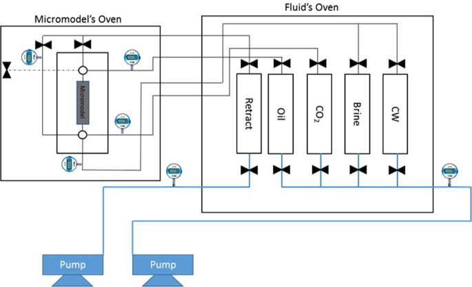
including CWI. To overcome this issue, direct visualization of fluid flows and interactions in the porous medium can be essential. In this study, a uniquely designed in-house micromodel rig,
with the ability to work at pressures as high as 10,000 psi and temperatures as high as 100 °C, was employed. Figure 1 shows the schematic of the micromodel rig. All fluids were kept inside
the fluid storage oven at test temperature and pressure. The micromodel was housed inside a separate oven under the same experimental condition. The micromodel was a transparent porous
medium made of two sapphire glass plates which was placed inside a high-pressure chamber. The high-pressure chamber provided the confining pressure on the micromodel. The confining pressure
was kept 400 psi higher than the pressure inside the micromodel at all times. One of the palates was etched with a pattern to allow fluids to flow in a controlled way and the other one was
unetched to seal the system. The pattern was a heterogeneous pattern synthesized in-house to lead to high residual oil saturation after a waterflood. The average pore depth of the micromodel
was 50 micrometers and the pore-throat diameters ranged from 300 to 500 micrometers. The depth of the pores was measured by a light scattering method. The micromodel dimensions are
summarized in Table 1. The porosity and pore size of the micromodel was measured by image analysis when the micromodel was fully saturated with blue-dyed water (Fig. 2). The permeability of
the micromodel was around 7 D. The glass walls of the micromodel provide the user with the direct observation of fluid flow and fluid-fluid interactions at the pore scale under high-pressure
and high-temperature conditions. To capture high-quality images and videos at the micro scale during flooding stages, a high-resolution microscope kit was used. The microscope had a
built-in fine focus. The kit was fixed at the desired position by utilizing a manual camera mount and positioning system. The camera was connected to a PC where Streampix software was used
for recording videos and pictures. In this study, micromodel experiments were conducted at a pressure and temperature of 2500 psi and 38 °C. FLUIDS PROPERTIES To address the effects of the
associated gas content of the oil, and different classes of hydrocarbons on the new gaseous phase, various oil types were used. Table 2 shows the list of utilized oils. Crude J is a medium
viscosity reservoir crude oil with the hydrocarbon composition and properties presented in Fig. 3A,B, respectively. The hydrocarbon composition of crude j was obtained by using a
high-resolution gas chromatograph with a flame ionization detector (FID). The viscosity and API of crude J are 86 cP and 20.87. Pure hydrocarbons, such as C6, C10, C16, C17, and C24 were
also used to investigate the roles of different classes of hydrocarbons on the new gaseous phase formation. Experiments 1 and 3 are similar to the experiments reported in the author’s
previous publications24,26,27,28. These experiments in combination with experiment 2 can provide insights into the role of the associated gas content of crude oil on the fluid-fluid
interactions occurring during carbonated brine injection. This was the reason for re-performing and reporting experiments 1 and 3 in this study. To saturate the oil types used in this study
with CH4, the oil was mixed with CH4 at 2450 psi and 38 °C. This 50 psi difference between the saturation pressure (2450 psi) of oils and the test pressure (2500 psi) would ensure no gas
liberation due to pressure variations. To prepare CW, a synthetic sea brine, with the ionic composition presented in Table 3, was mixed with CO2 with a purity of 99.99 mole % at 2450 psi and
38 °C. METHODOLOGY Having prepared the fluids, they were transferred to the fluid storage oven. Initially, the micromodel was fully saturated with brine (Table 3). Next the desired oil at
the rate of 0.1 cc/h, was injected into the micromodel to displace the water and establish the initial water saturation. The injection of oil was continued for several pore volumes until no
further changes in the fluids saturation and distribution was detected. Having established the initial water and oil saturation, to study the dynamic fluid-fluid interactions that happen
during CWI, the model was flooded with CW. The injection rate was 0.01 cc/h and the direction of injection was from the bottom of the micromodel toward its top. The injection of CW was
continued for around 24 hours. During each test, the micromodel was scanned by the high-resolution microscope kit to detect any possible fluid-fluid interactions at pore (micro) scale. For
further details about the experimental procedure, the reader is referred to the author’s previous publications27,28. RESULTS AND DISCUSSION The main objective of this study is to investigate
the dynamic phase behavior between CW and different oil types with the main focus being on the new gaseous phase. Since factors such as different oil viscosities could affect fluids flow in
the porous medium when different oils were used, fluid displacement and oil recoveries could not be comparatively investigated in this work. ROLES OF ASSOCIATE GAS CONTENT OF CRUDE OIL The
purpose of experiments 1 to 3 was to investigate the impacts of the associated gas content of crude oil on the new gaseous phase. Dead crude oil, partially (half) and fully-CH4 saturated
crude oils were used in these tests. Figure 4A–C show a magnified section of the micromodel after 10 hours of CWI in these three systems. As observed in Fig. 4A, the new gaseous phase did
not form during CWI in the dead oil system. Conversely, during CWI in partially CH4-saturated crude J system (Fig. 4B), after around 1 hour of CWI, small bubbles of a new gaseous phase
formed inside the oil phase and as the injection continued, their saturation increased. The yellow areas in Fig. 4B and other figures of this study highlight the new gaseous phase formed
during CWI. These results indicate that the presence of associated gas in crude oil is vital for the new gaseous phase formation. Figure 4C shows the same section of micromodel after 10
hours of CWI in a system where crude J was fully saturated with CH4. In this system, as soon as CW breakthrough happened, the new gaseous phase formed in the oil phase and as CWI continued
the saturation of the new gaseous phase increased. Comparison of the results of partially (half) and fully CH4-saturated crude J indicated the positive impact of associated gas content of
crude oil on the formation and growth of the new gaseous phase. Formation and growth of the new gaseous phase occurs faster and stronger for a given crude oil type when its associated gas
content is higher. ROLE OF OIL COMPOSITION The purpose of experiments 4 to 10 was to address the role of different classes of hydrocarbons on the new gaseous phase. In this study, oil
components were divided into two categories; i) oil components (i.e. C6 and C10) that are miscible, like first contact miscible (FCM) processes, with CO2 at test conditions, and ii) heavy
oil components (such as C16 and C17) which partially dissolve CO2. ROLE OF FIRST CONTACT MISCIBLE (FCM) OIL COMPONENTS To address the influence of FCM oil components on the new gaseous
phase, two different hydrocarbon components (C6 and C10), which are FCM with CO2 under the experimental condition, were used. Figure 5 shows a magnified section of the micromodel after 24
hours of CWI for two different systems including CH4-saturated C6 (Fig. 5A) and CH4-saturated C10 (Fig. 5B). During the long period of carbonated water injection (more than 40 hours) in
these systems, the new gaseous phase did not form. The only mechanism that improved the oil recovery was normal oil swelling which in turn led to oil reconnection and redistribution and
therefore further oil recovery. By using the Peng Robinson equation of states built in the PVT package of CMG software, the ternary system of CO2, CH4, and C6/C10 was analyzed. Since the
system under study is composed of pure components with known EOS parameters, the results of EOS analysis for these ternary systems are expected to be close to laboratory experiments31. In
the built model, the live oil was loaded into a cell and the temperature was set at 38 °C. The bubble point of the live oil was measured. Then, a small amount of CO2 was transferred into the
cell and a new saturation pressure was identified. This process was repeated for different CO2 mole fractions. Figure 6 shows the bubble point pressure of CH4-saturated C6/C10 versus CO2
concentration. As the CO2 mole fraction increased, the bubble points of live C6 and C10 decreased and always remained under the operating pressure of our tests (red line). Therefore, both
systems remained in the liquid phase. These trends shows that CO2 dissolution in CH4-saturated C6 and C10 do not lead to new gaseous formation which shows the unlimited solubility of CO2 in
these systems. The unlimited solubility of CO2 in these systems indicates first contact miscibility between CO2 and these live model oils. Consistent with modeling results, micromodel
experiments also showed that FCM oil components have an infinite capacity for dissolving CO2 in themselves while keeping CH4 in solution (Fig. 5). Therefore, CO2 mass transfer from CW into
these components does not have the potential to push the dissolved CH4 out of the solution and trigger the new gaseous phase formation. In other words, CO2 and CH4 dissolved in FCM
hydrocarbon components do not compete for remaining in solution (oil phase). As a result, FCM oil components are not responsible for triggering the formation of the new gaseous phase during
CWI in live oil systems. Furthermore, it can be concluded that the new gaseous phase would not be formed for those oil types that are FCM with CO2. This conclusion is regardless of the
associated gas content of these oil types. However, in real oil reservoirs, reservoir oils are seldom FCM with CO2; therefore, the new gaseous phase would be formed during CWI in oil fields
where oil has associated gases. To further study the role of FCM hydrocarbon components in a crude oil on the new gaseous phase, two different mixtures of crude J and C10 were prepared. The
first mixture was made of 30 wt% crude J and 70 wt% C10, and the second mixture was made of 50 wt% crude J and 50 wt% C10. Both mixtures were fully saturated with CH4. The modified crude
oils were not FCM with CO2. Figure 7 shows a section of the micromodel after establishing initial water and oil (30 wt% crude J + 70 wt% C10) saturation. The results of CWI for both modified
oils were compared with each other and with that of CH4-saturated crude J. Fig. 8 shows a magnified section of the micromodel after 10 hours of CWI in both modified oil systems. In both
tests, a unique behavior was observed. A high saturation of the new gaseous phase was surrounded by a thin black layer of oil. During both tests, the majority of the oil phase was extracted
into the new gaseous phase leading to a significant overall oil swelling. For these modified oils, as soon as CW came in contact with the oil phase, a rapid formation of gas bubbles in the
oleic phase was observed following by a strong extraction of the oil components into the new gaseous phase. This extraction enriched the new gaseous phase. In the micromodel, under
controlled experimental condition, a change in the oil quality can be detected based on the change in the oil color. The oil that is under extraction has a darker color compared to the
original oil27. Comparison of the color of original oil (Fig. 7) with that of CW-contacted oil (Fig. 8A) reveals the presence of this strong extraction. This behavior is due to the
enrichment of the new gaseous phase with CO226, which in turn leads to extraction of light to intermediate oil components into the new gaseous phase and its further enrichment. The observed
strong extraction from the oleic phase into the new gaseous phase significantly increased the saturation of the new gaseous phase. The saturation of the new gaseous phase during CWI in the
mixture of 30 wt% crude J + 70 wt% C10 (Fig. 8A) was higher than the mixture of 50 wt% crude J + 50 wt% C10 (Fig. 8B). This indicates that the new gaseous phase was mostly made of the
extracted C10. Table 4 presents the amounts of overall oil swelling for a trapped oil ganglion after 12 hours of CWI in experiments 3 and 6. Overall oil swelling is defined as:
$$\frac{{\rm{Final}}\,{\rm{volume}}\,{\rm{of}}\,{\rm{the}}\,{\rm{hydrocarbon}}\,\mathrm{phase}\,({\rm{oil}}+{\rm{new}}\,{\rm{phase}})-{\rm{Initial}}\,{\rm{volume}}\,{\rm{of}}\,{\rm{the}}\,{\rm{oil}}}{{\rm{Initial}}\,{\rm{volume}}\,{\rm{of}}\,{\rm{the}}\,{\rm{oil}}}\times
100$$ The strong extraction of C10 from modified crude oils into the new gaseous phase led to a significantly stronger overall oil swelling compared to the live crude J. This can positively
influence the extra oil recovery that can be obtained by CWI. Figure 9 shows the swelling of a trapped oil made of 70 wt% C10 and 30 wt% crude J during CWI. The reasons for such a
significant high overall oil swelling were the dynamic transfer of CO2 into the new gaseous phase and more importantly the strong extraction of the light to intermediate oil components into
the new gaseous phase. This strong swelling led to the reconnection of the trapped oil to other bypassed hydrocarbon phases and oil displacement. Based on the results of this section,
although FCM oil components in live reservoir crude oils are not responsible for triggering the new gaseous phase, they can lead to further growth of the new gaseous phase. As the new
gaseous phase is getting enriched with CO2, FCM oil components (light to intermediate hydrocarbon components) can be extracted into the new gaseous phase leading to further growth of the new
gaseous phase which in turn leads to a stronger overall oil swelling, oil reconnection and redistribution, and finally further oil recovery. This extraction was reported by micromodel tests
where extraction of light components (C4 and C3) led to _in-situ_ miscibility between the oil and the new gaseous phase29. The presence of this extraction was also confirmed by our PVT
experiments26 in which after a high volume of CW contacted live crude J, the formation of a small volume of the condensate was observed. Figure 10 shows the condensate composition. It should
be noted that the composition of condensate is a direct function of the oil composition. The condensate formed during CW-crude J PVT tests is mainly made of light to intermediate oil
components, in particular C10 and C12. Although the extraction of FCM oil components from the oil phase into the new gaseous phase helps to further its growth and thereby improve oil
recovery during CWI, this extraction has an adverse compositional effect over the quality of the remained oil. To investigate the impact of this extraction on the quality of the remained oil
after CWI, the micromodel was flooded with sea brine (Table 3). Through this final waterflooding step, the dissolved CO2 was stripped out of the remaining oil and the actual remaining oil
volume and color were detected. The rate of brine injection was 0.01 cc/h and brine was injected from the same head as CW was injected. During this step, no oil displacement was observed and
only the remaining oil ganglia were shrunken as their CO2 was extracted. Figure 11 compares the color of the remaining oil after CWI in experiments 3, 6 and 7, with their original oil
color. In experiments 6 and 7, where C10 content of crude oil was enhanced, the formation and growth of the new gaseous phase led to a very strong oil recovery, while at the same time
leading to an adverse oil compositional effect. Conversely, for fully CH4-saturated crude J, formation and growth of the new gaseous phase did not cause any detectable negative effect on the
oil composition and the remaining oil looked similar to its initial condition. This shows that the negative impact of extraction of light hydrocarbon components into the new gaseous phase
is a direct function of the light components content of the crude oil. For crude oils with higher amounts of light hydrocarbon components, during CWI the extraction to the new gaseous phase
will be stronger, and thereby oil quality would be more affected. ROLE OF HEAVY OIL COMPONENTS To adequately investigate the impact of heavy oil components on the new gaseous phase during
CWI, experiments 8 to 10 were carried out. Figures 12, 13 and 14 present a magnified section of the micromodel after 10 hours of CWI in the model saturated with C16, C17 and a mixture of 77
wt% C17 and 23 wt% C24, respectively. The employed oils were fully saturated with CH4 under the experimental conditions. CWI in these systems led to the rapid formation of the new gaseous
phase inside the oleic phase. Based on these observations, it can be concluded that heavy hydrocarbon components are in charge of triggering the formation of the new gaseous phase since they
have a limited capacity for holding both CH4 and CO2 in their own. Therefore, a competition exists between CH4 and CO2 to remain in the solution (oil phase) which in turn leads to the
formation of the new gaseous phase. As seen from Figs 12, 13 and 14, formation and growth of the new gaseous phase for the case of live oil mixture (77 wt% C17 and 23 wt% C24) was stronger
than live C17 and for live C17 was stronger than live C16. This behavior was observed while the associated gas content of the live oil mixture (77 wt% C17 and 23 wt% C24) was less than live
C17 and the associated gas content of live C17 was less than live C16 under the experimental conditions. As a result, the associated gas content of the oil is not the only factor that
controls the strong and fast formation of the new gaseous phase. Therefore, for two different live reservoir crude oils, the one with higher associated gas content does not necessarily have
the stronger formation of the new gaseous phase during CWI. The impact of oil composition must be considered alongside its associated gas content. Based on our observations, during CWI in
the micromodel saturated with a CH4-saturated mixture of 77 wt% C17 and 23 wt% C24, the new gaseous phase formed ahead of the CW front in the porous media, while during CWI in the micromodel
saturated with either CH4-saturated C17 or CH4-saturated C16, the new gaseous phase formed slightly after CW breakthrough. These observations revealed the role of each component on
formation of the new gaseous phase. For the heavier oil components, the onset of new gaseous phase formation is sooner. This is attributed to the smaller capacity of heavier oil components
for holding both CO2 and CH4 in solution compared to intermediate components. Consequently, it can be inferred that, during CWI, due to CO2 transfer from CW into the crude oil, the heavy oil
components tend to release their dissolved CH4 which triggers the formation of the new gaseous phase. CONCLUSION Based on the results of this study, it can be concluded that the presence of
dissolved gas in oil is essential for the formation of the new gaseous phase during carbonated water injection. However, regardless of the dissolved gas content of the oil, if the oil is
first contact miscible with CO2 at reservoir conditions such as light model oils, the new gaseous phase would not be formed. Light to intermediate hydrocarbon components of a crude oil
facilitate further growth of the new gaseous phase as they can be extracted into the new gaseous phase while heavy hydrocarbon components are responsible for the formation of the new gaseous
phase. The observed _in situ_ new gaseous phase formation would be more profound in live crude oils, at or close to their bubble points, with a higher amount of first contact miscible
hydrocarbon components, which can control the CO2 dissolution into the oil as well as the further growth of the new gaseous phase. Small quantities of heavy components would suffice for
triggering the new gaseous phase formation and continuous feed of dissolved CO2 would lead to the favorable growth of the new gaseous phase. Therefore, as long as the injection of carbonated
water continues and CO2 partitions from carbonated water into the trapped oil in the porous media, the saturation of the new gaseous phase inside the oil phase increases. DATA AVAILABILITY
All data generated or analyzed during this study are included in this published article. REFERENCES * Sohrabi, M. _et al_. Coreflooding Studies to Investigate the Potential of Carbonated
Water Injection as an Injection Strategy for Improved Oil Recovery and CO2 Storage. _Transp Porous Media._ 91(1), 101–121, https://doi.org/10.1007/s11242-011-9835-5 (2012). Article CAS
Google Scholar * Burton, M. & Bryant, S. L. Eliminating Buoyant Migration of Sequestered CO2 Through Surface Dissolution: Implementation Costs and Technical Challenges. _SPE Reserv Eval
Eng._ 12(03), 399–407, https://doi.org/10.2118/110650-pa (2009). Article CAS Google Scholar * Riazi, M. & Sohrabi, M. Oil recovery improvement using CO2-enriched water injection.
_SPE Eur Annu Conf Exhib_ (2009). * Kechut, N. I., Jamiolahmady, M. & Sohrabi, M. Experimental and Numerical Evaluation of Carbonated Water Injection (CWI) for Improved Oil Recovery and
CO2 Storage. _Proc SPE Eur Annu Conf Exhib._ 77, 111–120, https://doi.org/10.1016/j.petrol.2011.02.012 (2011). Article CAS Google Scholar * Perez, J. M., Poston, S. W. & Sharif, Q. J.
Carbonated Water Imbibition Flooding: An Enhanced Oil Recovery Process for Fractured Reservoirs. _Proc SPE/DOE Enhanc Oil Recover Symp_., https://doi.org/10.2523/24164-MS (1992). * Kechut,
N. I., Riazi, M., Sohrabi, M. & Jamiolahmady, M. Tertiary Oil Recovery and CO2 Sequestration by Carbonated Water Injection (CWI), https://doi.org/10.2118/139667-ms (2011). * Sohrabi, M.,
Tavakolian, M., Emadi, A., Jami, M. & Ireland, S. Improved Oil Recovery and Injectivity By Carbonated Water Injection 1–12 (2012) * Riazi, M., Sohrabi, M. & Jamiolahmady, M.
Experimental Study of Pore-Scale Mechanisms of Carbonated Water Injection. _Transp Porous Media._ 86(1), 73–86, https://doi.org/10.1007/s11242-010-9606-8 (2011). Article CAS Google Scholar
* Sohrabi, M. _et al_. Carbonated Water Injection (CWI) - A productive way of using CO2 for oil recovery and CO2 storage. _Energy Procedia._ 4, 2192–2199,
https://doi.org/10.1016/j.egypro.2011.02.106 (2011). Article CAS Google Scholar * Sohrabi, M., Riazi, M. & Jamiolahmady, M. Carbonated water injection (CWI) studies. Enhanc Oil
….(April 2014), http://www.pet.hw.ac.uk/research/hrm/cwi/papers/2008_iea.pdf. (2008). * Enhanced Oil Recovery and CO2 Storage by Carbonated Water Injection. Technology. 14070 (2009). *
Mosavat, N. & Torabi, F. Experimental evaluation of the performance of carbonated water injection (CWI) under various operating conditions in light oil systems. _Fuel._ 123, 274–284,
https://doi.org/10.1016/j.fuel.2014.01.077 (2014). Article CAS Google Scholar * Robertson, G. _et al_. Safe storage of Co2 together with improved oil recovery by Co2-enriched water
injection. _Chem Eng Res Des._ 89(9), 1865–1872, https://doi.org/10.1016/j.cherd.2011.01.027 (2011). Article CAS Google Scholar * Seyyedi, M. & Sohrabi, M. Enhancing Water Imbibition
Rate and Oil Recovery by Carbonated Water in Carbonate and Sandstone Rocks. _Energy and Fuels._ 30(1), 285–293, https://doi.org/10.1021/acs.energyfuels.5b02644 (2016). Article CAS Google
Scholar * Riazi, M., Jamiolahmady, M. & Sohrabi, M. Theoretical investigation of pore-scale mechanisms of carbonated water injection. _J Pet Sci Eng._ 75(3-4), 312–326,
https://doi.org/10.1016/j.petrol.2010.11.027 (2011). Article CAS Google Scholar * Sohrabim, M., Riazi, M. & Jamiolahmady, M. Mechanisms of oil recovery by carbonated water injection.
SCA Annu …. (January):1–12, http://www.scaweb.org/assets/papers/2009_papers/SCA2009-26.pdf (2009). * Mosavat, N. & Torabi, F. Micro-optical analysis of carbonated water injection in
irregular and heterogeneous pore geometry. _Fuel._ 175, 191–201, https://doi.org/10.1016/j.fuel.2016.02.039 (2016). Article CAS Google Scholar * Dong, Y., Ishizawa, C., Lewis, E. &
Dindoruk, B. Carbonated Water Flood: What We Observed in Sand Pack Experiments. _Int Symp Soc Core Anal held Austin_, _Texas_, _18–21 Sept_. 1–12 (2011). * Mosavat, N. & Torabi, F.
Application of CO2 -Saturated Water Flooding as a Prospective Safe CO2 Storage Strategy. _Energy Procedia._ 63, 5408–5419, https://doi.org/10.1016/j.egypro.2014.11.571 (2014). Article CAS
Google Scholar * Mosavat, N. & Torabi, F. Performance of secondary carbonated water injection in light oil systems. _Ind Eng Chem Res._ 53(3), 1262–1273,
https://doi.org/10.1021/ie402381z (2014). Article CAS Google Scholar * Alizadeh, A. H., Khishvand, M., Ioannidis, M. A. & Piri, M. Multi-scale experimental study of carbonated water
injection: An effective process for mobilization and recovery of trapped oil. _Fuel._ 132, 219–235, https://doi.org/10.1016/j.fuel.2014.04.080 (2014). Article CAS Google Scholar * Zuo, L.
& Benson, S. M. Exsolution enhanced oil recovery with concurrent CO2 sequestration. _Energy Procedia._ 37, 6957–6963, https://doi.org/10.1016/j.egypro.2013.06.629 (2013). Article CAS
Google Scholar * Sohrabi, M., Emadi, A., Farzaneh, S. A., Ireland, S. & Oil, E. A Thorough Investigation of Mechanisms of Enhanced Oil Recovery by Carbonated Water Injection,
https://doi.org/10.2118/175159-MS (2015). * Seyyedi, M., Sohrabi, M. & Sisson, A. Experimental investigation of the coupling impacts of new gaseous phase formation and wettability
alteration on improved oil recovery by CWI. _J Pet Sci Eng._ 150(November 2016), 99–107, https://doi.org/10.1016/j.petrol.2016.11.016 (2017). Article CAS Google Scholar * Seyyedi, M.,
Sohrabi, M., Sisson, A. & Ireland, S. Quantification of oil recovery efficiency, CO2 storage potential, and fluid-rock interactions by CWI in heterogeneous sandstone oil reservoirs. _J
Mol Liq._ 249, 779–788, https://doi.org/10.1016/j.molliq.2017.10.070 (2018). Article CAS Google Scholar * Seyyedi, M., Mahzari, P. & Sohrabi, M. An integrated study of the dominant
mechanism leading to improved oil recovery by carbonated water injection. _J Ind Eng Chem._ 45, 22–32, https://doi.org/10.1016/j.jiec.2016.08.027 (2017). Article CAS Google Scholar *
Seyyedi, M., Mahzari, P. & Sohrabi, M. A comparative study of oil compositional variations during CO2 and carbonated water injection scenarios for EOR. _J Pet Sci Eng._ 164(August 2017),
685–695, https://doi.org/10.1016/j.petrol.2018.01.029 (2018). Article CAS Google Scholar * Seyyedi, M. & Sohrabi, M. Pore-Scale Investigation of Crude Oil/CO2 Compositional Effects
on Oil Recovery by Carbonated Water Injection, https://doi.org/10.1021/acs.iecr.6b04743 (2017). Article CAS Google Scholar * Mahzari, P. _et al_. Carbonated water injection under
reservoir conditions; _in-situ_ WAG-type EOR. _Fuel._ 217(June 2017), 285–296, https://doi.org/10.1016/j.fuel.2017.12.096 (2018). Article CAS Google Scholar * Ahmed, T. Fundamentals of
Reservoir Fluid Flow. _Work Guid to Reserv Rock Prop Fluid Flow_. 117–246, https://doi.org/10.1016/b978-1-85617-825-9.00003-x (2013) Chapter Google Scholar * Nemati Lay, E., Taghikhani, V.
& Ghotbi, C. Measurement and correlation of CO2 solubility in the systems of CO2+ toluene, CO2+ benzene, and CO2+ n-hexane at near-critical and supercritical conditions. _J Chem Eng
Data._ 51(6), 2197–2200, https://doi.org/10.1021/je0602972 (2006). Article CAS Google Scholar Download references ACKNOWLEDGEMENTS This work was carried out as part of the ongoing
Enhanced Oil Recovery by Carbonated Water Injection (CWI) joint industry project (JIP) in the Institute of Petroleum Engineering of Heriot-Watt University. The project is equally sponsored
by ADCO, BG Group, Eni, Galp Energia, Oil India, and the UK DECC, which is gratefully acknowledged. AUTHOR INFORMATION AUTHORS AND AFFILIATIONS * Centre for Enhanced Oil Recovery and CO2
solutions, Heriot-Watt University, Edinburgh, United Kingdom Mojtaba Seyyedi & Mehran Sohrabi * CSIRO Energy, Australian Resources Research Centre (ARRC), 26 Dick Perry Avenue,
Kensington, WA, 6151, Australia Mojtaba Seyyedi * Department of Earth Sciences, University College London, London, United Kingdom Pedram Mahzari Authors * Mojtaba Seyyedi View author
publications You can also search for this author inPubMed Google Scholar * Pedram Mahzari View author publications You can also search for this author inPubMed Google Scholar * Mehran
Sohrabi View author publications You can also search for this author inPubMed Google Scholar CONTRIBUTIONS Most of this work was done by the first author (Dr. Mojtaba Seyyedi). Dr. Seyyedi
performed and analysed the experiments and wrote the main draft. Dr. Mahzari and Prof. Sohrabi provided invaluable technical supports and helped in writing the paper. CORRESPONDING AUTHOR
Correspondence to Mojtaba Seyyedi. ETHICS DECLARATIONS COMPETING INTERESTS The authors declare no competing interests. ADDITIONAL INFORMATION PUBLISHER’S NOTE: Springer Nature remains
neutral with regard to jurisdictional claims in published maps and institutional affiliations. RIGHTS AND PERMISSIONS OPEN ACCESS This article is licensed under a Creative Commons
Attribution 4.0 International License, which permits use, sharing, adaptation, distribution and reproduction in any medium or format, as long as you give appropriate credit to the original
author(s) and the source, provide a link to the Creative Commons license, and indicate if changes were made. The images or other third party material in this article are included in the
article’s Creative Commons license, unless indicated otherwise in a credit line to the material. If material is not included in the article’s Creative Commons license and your intended use
is not permitted by statutory regulation or exceeds the permitted use, you will need to obtain permission directly from the copyright holder. To view a copy of this license, visit
http://creativecommons.org/licenses/by/4.0/. Reprints and permissions ABOUT THIS ARTICLE CITE THIS ARTICLE Seyyedi, M., Mahzari, P. & Sohrabi, M. A Fundamental Micro Scale Study of the
Roles of Associated Gas Content and Different Classes of Hydrocarbons on the Dominant Oil Recovery Mechanism by CWI. _Sci Rep_ 9, 5996 (2019). https://doi.org/10.1038/s41598-019-42226-6
Download citation * Received: 17 April 2018 * Accepted: 20 March 2019 * Published: 12 April 2019 * DOI: https://doi.org/10.1038/s41598-019-42226-6 SHARE THIS ARTICLE Anyone you share the
following link with will be able to read this content: Get shareable link Sorry, a shareable link is not currently available for this article. Copy to clipboard Provided by the Springer
Nature SharedIt content-sharing initiative