- Select a language for the TTS:
- UK English Female
- UK English Male
- US English Female
- US English Male
- Australian Female
- Australian Male
- Language selected: (auto detect) - EN
Play all audios:
ABSTRACT The corrosion failure of amorphous carbon (a-C) coatings is commonly ascribed to the existence of growth microdefects, which serve as pathways for corrosive fluids to permeate the
substrate. Atomic layer deposition (ALD) is renowned for its ability to augment the corrosion resistance of metallic materials. Graphite-like carbon (GLC) is one of the amorphous carbon
materials dominated by hybridized sp2-C bonds. In this study, an ALD-deposited Al2O3 layer is specially introduced on the Cr/GLC multilayer coating to solve the aforementioned corrosion risk
of a-C by taking the sealing conception for defects. Compared to the as-deposited Cr/GLC coating, the coating encapsulated with Al2O3 layer depicts the reduction of corrosion current
density over two orders of magnitude under a wide pressure range of 0.1 ~ 15 MPa. Particularly, the presence of released Crn+ and Fen+ in the corrosion solution is significantly diminished,
accompanying with a small quantity of Aln+ generated in sealed coating during corrosion. Microstructural analysis and electrochemical results identified that both the dense Al2O3 layer
offered strong safeguard for Cr elements released from multilayers, whilst amorphous carbon network inhibited the likelihood chloride penetration induced by partially infiltrated Al2O3,
which made the synergistic contributions to the enhancement of corrosion resistance for Cr/GLC coating for deep-sea applications. SIMILAR CONTENT BEING VIEWED BY OTHERS AL2O3-MODIFIED 7YSZ
THERMAL BARRIER COATINGS FOR PROTECTION AGAINST VOLCANIC ASH CORROSION Article Open access 10 November 2022 GREEN AND SUSTAINABLE CHITOSAN–GUM ARABIC NANOCOMPOSITES AS EFFICIENT
ANTICORROSIVE COATINGS FOR MILD STEEL IN SALINE MEDIA Article Open access 01 August 2022 ELECTROCHEMICAL AND HOT CORROSION BEHAVIOUR OF ANNEALED ALCOCRFENI HEA COATING OVER STEEL Article
Open access 07 March 2024 INTRODUCTION Marine engineering equipment plays a fundamental role in driving the progress of the maritime economy, where the innovation in state-of-the-art marine
relevant machinery and sophisticated vessels has become a focal point for achieving breakthroughs in marine development1,2. In general, these cutting-edge systems face a myriad of
challenges, including corrosion, tribocorrosion, erosion, biofouling, and the interconnected impact of these factors3,4. Particularly, many moving components used for marine engineering not
only endure a harsh corrosive environment, but also confront demanding conditions like highly hydrostatic pressure and strongly chloride corrosion during operations, rendering the materials
vulnerable to be degraded and dangerous disaster5,6,7,8. These challenges are particularly decisive for the friction components, such as the ship propeller bearings, submarine buoyancy
adjustment part, underwater robot joints, seawater hydraulic system piston pumps, deep-sea drilling lifting and sinking compensation devices. The degradation of corrosion resistance could be
clearly evidenced for conventional metallic materials and polymer-based organic coatings under deep-sea environments9,10. Consequently, an urgent demand arises for the development of a
genre of highly corrosion-resistant coatings combined with other remarkably mechanical and tribological properties. Amorphous carbon coating (a-C) is a well-known form of amorphous thin film
composed of hybridized sp2 carbon bonds and sp3 bonds11. The graphite-like carbon (GLC) coating is a type of a-C material, especially characterized by a higher content of sp2 carbon bonds.
Thanks to the exceptional attributes of high hardness, superior lubrication and exemplary resistance to corrosion, a-C coatings enable them immense applications in aerospace, automotive, and
marine related equipment. More specifically, they are envisioned to serve as an exquisite protective shielding for the vital moving components of offshore equipment12,13,14,15,16. However,
noted that even these a-C coatings possess outstanding chemical stability in seawater, it is imperative to acknowledge the existence of inherent growth imperfections within the structural
network. As an evident observation, such blemishes directly compromise the corrosion resistance and protective performance of a-C films17. Conventional methods, notably physical vapor
deposition (PVD), employed in the fabrication of a-C coatings often yield the manifestation of growth defects during the deposition process, in which the discernible defects mainly are
dominated by nodular defects, pinholes, and even porous penetrations18. Once the a-C coatings are exposed to the corrosive media, such defects can easily facilitate the penetration of
corrosive electrolytes to substrate, thereby instigating anodic reactions at relevantly vulnerable sites and leading to seriously localized corrosion19,20. As a result, it becomes a strong
driving force to develop a coating system that exhibits minimal imperfections while upholding superior resistance against corrosion and lubrication. In order to overcome the aforementioned
bottlenecks, various strategies have been attempted to enhance the densification of coatings20,21,22,23,24. By introducing the multilayer structure, Li et al. successfully fabricated the
Cr/GLC coatings by a hybrid magnetron sputtering technique, where the corrosion resistance of GLC was significantly enhanced due to the suppressed penetration defects at 0.1 MPa, without
simultaneous deterioration of other mechanical and tribological properties22,25. Nevertheless, different with the atmospheric condition, the protective degradation of coating was
subsequently observed under high hydrostatic pressure of 30 MPa because of the defects propagation from the substrate17. To evidence this conclusion, the extra-cleaning intervention was
further operated to reduce the nodular defects during the deposition of Cr/GLC coatings. The results demonstrated that comparing with pristine Cr/GLC coating, the cleaned coating reduced the
corrosion current density about 50 times after immersion into 3.5 wt.% NaCl solution for 300 h with a simulated high hydrostatic pressure (31 MPa)20. Very recently, taking the contribution
from high power impulse magnetron sputtering (HiPIMS) with high ionization and large incident energy, the densely GLC coating combined with Cr interlayers was achieved. Comparing to Cr/GLC
coating deposited by traditional DC magnetron sputtering, HiPIMS-deposited Cr/GLC coatings clearly enhanced the corrosion resistance under a simulated dee-sea environments24. Considering the
life-time required for offshore equipment in marine, densification of a-C coating is still necessary to prolong the protective performance with inhibition of corrosive penetrating to
substrate. Fortunately, atomic layer deposition (ALD) has been an alternatively growing fascination in the context of sealing defects directly23,26,27. This technique enables the deposition
of a protective oxide film at the atomic-scale, ensuring exceptional uniformity and impeccable densification28,29. For instance, Leppäniemi et al. reported the power of ALD layer to modify
CrN coatings, in which a remarkable reduction in corrosion current density was indicated. Interestingly, even after the removal of the top ALD layer, the corrosion current density of CrN was
remained about 50% lower than that of unsealed CrN, identifying how certain defects in PVD coatings were distinctly sealed by further applied ALD process26. This observation acted as
undeniable contribution from ALD method in sealing defects of various pinhole or nodular sizes on the surface of coatings. Taking the conception of sealing advantages, in this study, we
fabricated the Cr/GLC multilayered coatings by a hybrid direct current magnetron sputtering deposition system, and introduced an extra Al2O3 top-layer over the coating surface by ALD
technique. The comprehensive examinations were conducted to identify the evolution of interfacial structure between Al2O3 layer and Cr/GLC coatings. The corrosion resistance and
electrochemical behavior before and after sealing were comparatively investigated in a high hydrostatic pressure with chloride solutions to emulate the deep-sea marine environment. The
scanning vibrating electrode technique (SVET) was particularly employed to address the localized corrosion state occurred at the coated surface for the understanding on the failure mechanism
of combined coatings with controlled encapsulating. The Cr/GLC coatings without and with Al2O3 sealing were designated as S1 and S2 in the following sections, respectively. RESULTS AND
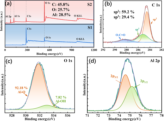
DISCUSSION MICROSTRUCTURAL EVOLUTION In order to investigate the changes of chemical structure, the Cr/GLC coating with and without Al2O3 sealing was characterized through X-ray
photoelectron spectroscopy (XPS) for comparison. Figure 1a shows the XPS spectra of S1 and S2, respectively. Both S1 and S2 samples exhibited C 1s, O 1s, and O KLL peaks in the respective
spectra correspondingly. Noted that, however, the spectrum of the S2 coating revealed the presence of Al 1s and 2p peaks, accompanying with a significantly increment in the intensity of O 1s
peak. This observation strongly suggested that the deposition of Al2O3 layer was successfully achieved on the surface of Cr/GLC multilayer coating. As evidenced in Fig. 1b–d, all the C 1s,
O 1s, and Al 2p spectra obtained from S2 were primarily originated from the topmost layer combined with Cr/GLC coating. The XPS calibration using the binding energy of C1s (284.8 eV). The C
1s The C 1s spectrum was further deconvoluted into three distinct components: a sp3 C-C bond at 285.2 ± 0.2 eV, a sp2 C = C bond at 284.4 ± 0.2 eV, and an O-C = O bond assigned to 288.2 ±
0.2 eV17. Therefore, the percentages of sp2, sp3, and O-C = O bonds were determined to be 59.19%, 29.44%, and 11.37%, respectively. Likewise, the O 1 s spectrum underwent deconvolution with
two different peaks: Al-O at 531.8 ± 0.2 eV and Al-OH at 533.4 ± 0.2 eV. During the reaction between trimethylaluminum (TMA) and water (H2O), the methyl groups (-CH3) were replaced by
hydroxyl groups (-OH), leading to the formation of Al-OH bonds with CH4. Nevertheless, due to incomplete reaction of TMA, some of Al-OH bonds were trapped within the Al2O3 structure30. The
contents of Al-O and Al-OH bonds were 92.18% and 7.82%, respectively. The dominant peak displayed in the Al 2p spectrum at approximately 74.8 ± 0.2 eV could be further resolved into Al 2p3/2
at 74.5 ± 0.2 eV and Al 2p1/2 at 75.2 ± 0.2 eV. These values also proposed the presence of O-Al-O bonds. Based on the above analysis, it could be reasonable said that both O and Al species
emerged on the surface of the Cr/GLC coating, predominantly in the form of Al2O3 phases, corresponding to the successful encapsulating of Al2O3 for Cr/GLC coating31. SURFACE AND
CROSS-SECTIONAL MORPHOLOGIES Figure 2 shows the representative transmission electron microscopy (TEM) and elemental mapping of the Cr/GLC coating with Al2O3 sealing layer. The selection
image was specifically focused on the defect location for evaluating the encapsulated influence of Al2O3. Figure 2a depicts the presence of penetration defects inclined towards the edge of
the coating, in which dark gray and light gray shades illustrated the Al2O3 layer and GLC, respectively. Clearly, the Al2O3 layer exhibited the exceptional uniformity with a thickness of
approximately 45 nm. In addition, noted that the Al2O3 layer represented the typical amorphous characteristics of short-range order and long-range disorder, which was also evidenced by the
diffused halo diffraction rings. Moreover, this feature could be identified from the fast Fourier Transform (FFT) analysis of the TEM images in Fig. 2a. The selected area electron
diffraction (SAED) results of the Al2O3 layer revealed the typical amorphous structures for the outmost encapsulation. The Cr/GLC coating demonstrated a clear laminar structure with a
well-established Cr/C interface (Fig. 2b). According to the localized magnification of interfaces between Al2O3 and GLC layers, the distribution of Cr and O elements were bonded coherently,
owing to the formation of chromium oxide through their interactions amidst ambient air. Meanwhile, both O and Al elements were detected above the GLC layer, extending into the next Cr layer.
This phenomenon strongly suggested that the Al2O3 not only was densely deposited the surface of the Cr/GLC coating but also infiltrated the defects with an outstandingly penetrative effect
without expectation. Figure 3 illustrates the plan view morphology and three-dimensional morphology image by atomic force microscopy (AFM) measurement for S1 and S2 samples. All the coatings
illustrated a continuous, uniform and smooth surface morphology regardless of Al2O3 encapsulating, despite the cauliflower shaped protrusions were visible from the coating surfaces. Due to
the continued growth of amorphous carbon along the transition layer or substrate surface structure. For S1 and S2 samples, the _R_q value of coating was slighted reduced from 13.3 nm to 12.3
nm before and after Al2O3 sealing process. The reason could be arisen from the densely amorphous overcoated Al2O3 facilitated by ALD technique. Since atomic layer deposition (ALD)
technology is a conformal process to produce the continuously dense Al2O3 layer32, it can be suspected that introducing the Al2O3 sealing layer enables the defect encapsulating for the
pristine Cr/GLC coating, consequently benefiting the smoothness increment in coating. However, the 45 nm-thickness Al2O3 layer was too thin to conquer the cluster-shape surface of Cr/GLC
coating, as identified by the slight decrease of _R_q only around 1 nm. EIS ANALYSIS To address the effect of Al2O3 sealing on the corrosion resistance of the Cr/GLC coating, EIS analysis
was performed specially in a 3.5 wt. % NaCl solution under pressures of 0.1 MPa and 15 MPa. Figure 4a, b show the Nyquist plots and Bode plots, respectively, along with the respective fitted
curves. All Nyquist plots exhibited a striking capacitance loop alongside a linear segment spanning the entire frequency spectrum, suggesting a defensive capacity against hydrostatic
corrosion. From the enlarged image, the arc radius of the capacitances for both S1 and S2 decreased at pressure of 15 MPa than those at 0.1 MPa. However, comparing to S1 sample without
sealing, the S2 sample still maintained a larger capacitance arc radius, indicating the outstanding corrosion resistance even under high hydrostatic pressure. Generally, the EIS displayed a
substantial phase angle (φ), indicative of the material’s strong capacitance characteristic, particularly in the intermediate frequency phase angle33. For the S1 sample lacking Al2O3
sealing, at 0.1 MPa, the φ value approached approximately 80° within the mid-frequency region, denoting commendable corrosion resistance. Nevertheless, when subjected to a higher hydrostatic
pressure of 15 MPa, a noticeable overall downward shift in φ occurred due to the facile permeation of corrosive fluid through surface defects, thereby deteriorating the protective
capability of the coating. In contrast, following the Al2O3 sealing of the Cr/GLC surface, the φ value maintained near 90° across the frequency range in 0.01 ~ 10,000 Hz at 0.1 MPa,
revealing the outstanding corrosion stability. Increasing the hydrostatic pressure to 15 MPa caused a distinct decline in the φ value at 2 Hz for S2, probably due to the corrosive
fluctuations from the encapsulated Al2O3 layer. The hydrostatic pressure contributed to the deterioration of the Al2O3 layer by augmenting the activity of adsorbed Cl− ions on the sample
surface, thus facilitating the dissolution of Al2O3. As the hydrostatic pressure ascended from 0.1 MPa to 15 MPa, the impedance values of S1 and S2 decreased from 1.79 × 10⁶ Ω·cm2 and 3.89 ×
108 Ω·cm2 to 6.79 × 10⁵ Ω·cm2 and 6.86 × 10⁷ Ω·cm2, respectively. Moreover, it was worth mentioning that the impedance values of S2 under different hydrostatic pressures were larger than
those of S1, indicating that the hermeticity of ALD-deposited Al2O3 film greatly improved the corrosion resistance of the Cr/GLC coating at pressure of 0.1 ~ 15 MPa. The EIS fitting data for
S1 and S2 were fitted using the equivalent circuit, as shown in the inset of Fig. 4a. In this circuit, _R_s symbolized the electrolyte resistance, _R_ct represented the charge transfer
resistance, and _CPE_dll was assigned to the double-layer capacitance. Additionally, _R_po and _CPE_c denoted the pore resistance and capacitance of the coating, respectively. To account for
the “scattering effect” in the coating system, a constant phase element (_CPE_) was employed instead of a pure capacitance17. The values of the electric double layer capacitance, _CPE_dll,
were calculated by Brug’s formula34. The values of the _CPE_c were calculated based on the work from Hsu’s and Mansfeld’s studies35. Table 1 presented the fitting parameters obtained from
the EIS analysis. _CPE_c, which stands for capacitance of the coating, was widely recognized in relation to the porosity of the coating. Referring to the empirical equations20, a higher
magnitude of _CPE_c signified a rapid corrosion process during immersion, which could be intricately linked to the chemical composition and microstructure of the multilayer coating system.
Following the 15 MPa immersion, the _CPE_c of the S1 experienced an elevation from 7.88 × 10⁻⁶ F·cm−2 to 1.08 × 10⁻⁶ F·cm−2. On the other hand, the _CPE_c of S2 increased from 3.89 × 10⁻⁸
F·cm−2 to 1.69 × 10⁻⁷ F·cm−2. Since the _CPE_c in this context was largely influenced by the exposed area of the active region and the porosity of the coating, the findings revealed that the
Al2O3 sealing effectively mitigated defects in the coating, thus diminishing the potential for interface corrosion between the Cr layer and the GLC layer24. Taking into consideration the
evolution of _CPE_dll, Table 1 elucidated the corrosive reaction observed between the substrate and coating. Compared to S1, S2 manifested a smaller value of _CPE_dll under the influence of
high hydrostatic pressure amounting to 15 MPa, implying a comparatively feeble corrosion reaction transpiring at the interface17. At a hydrostatic pressure of 15 MPa, the value of _R_po for
S1 was surprisingly low, approximately five orders of magnitude smaller than that at 0.1 MPa. This observation proposed the existence of defects in the Cr/GLC coatings, which could yield the
penetration of corrosive fluids under high hydrostatic pressures. Conversely, the Cr/GLC coating sealed with Al2O3 layer displayed virtually no reduction in _R_po under 15 MPa. In general,
it was empirically known that _R_ct was signified the rate of charge transfer at the interface between substrate and electrolyte solution, the higher values of _R_ct indicated a slower
corrosion reaction within the system. In comparison to S1, the value of _R_ct for S2 was three orders of magnitude larger under different hydrostatic pressures, reflective of the excellent
ability to impede the flow of corrosive fluids. According to these aforementioned variations in the fitting results, S2 sample possessed an extremely high level of compactness and performed
the exemplary resistance against chloride corrosion for deep-sea application due to the encapsulated Al2O3 layer. Meanwhile, Dense Al2O3 mitigated the potential for interface corrosion
between the Cr layer and the GLC layer by minimizing the infiltration of corrosive fluids. POLARIZATION TESTS Figure 4c shows the potentiodynamic polarization curves for samples S1 and S2,
under hydrostatic pressures of 0.1 MPa and 15 MPa, respectively. The relevant fitting outcomes are also presented in Table 1. For comparison, it was evident that at 0.1 MPa, the _i_corr
values for S1 was stabilized at 7.38 × 10⁻⁷ A·cm−2, whereas that of S2 stabilized at a significantly lower value of 7.5 × 10⁻¹⁰ A·cm−2, approximately three orders of magnitude below that of
S1. In this aspect, it could be said that the capability of corrosion resistance in S2 sample was much stronger than that in S1 case. Nevertheless, with increment of the hydrostatic pressure
to 15 MPa, the corresponding _i_corr values for both S1 and S2 increased to 9.25 × 10⁻⁷ A·cm−2 and 1.39 × 10⁻⁹ A·cm−2, respectively, indicating a slight decline in the corrosion resistance
of both samples. Furthermore, the corrosion potential (_E_corr) for sample S2 at 0.1 MPa was determined to be −0.304 V, which displayed a cathodic shift when compared to sample S1 at both
0.1 MPa and 15 MPa. The reason behind of this phenomenon could be attributed to the obstructive benefits of S2 on the diffusion of chloride, water and dissolved oxygen, resulting in reduced
cathodic current and a shift towards the cathodic region of the _E_corr at 0.1 MPa36. Such observation further confirmed that the S2 specimen possessed the lower defect density and superior
capability in impeding the permeation of water and dissolved oxygen. Noted that, however, under the hydrostatic pressure of 15 MPa, the _E_corr of S2 experienced an anodic shift in contrast
to that at 0.1 MPa, primarily because of the accelerated penetration of dissolved oxygen and water combined with chloride ions17. Additionally, the corrosion current densities of cathodic
domain for both S1 and S2 at 0.1 MPa were inferior to those observed at 15 MPa, which agreed well with the aforementioned analysis. Notably, in the cathodic region, the discussion was mainly
revolved around the reduction of dissolved oxygen and water in neutral solutions, rather than chloride ions, as they were the principal factors driving cathodic corrosion36. In the anodic
region, the corrosion current density (_i_corr) of sample S1 exhibited a slight incline, lacking of any obvious indications of pitting corrosion, epitomizing the typical behavior observed in
the anodic region of GLC coatings. Prior to reaching a voltage of 1.1 V at both 0.1 MPa and 15 MPa, there was negligible disparity in the _i_corr values of S1. Beyond of 1.1 V, however, the
_i_corr considerably escalated at 15 MPa, indicating the accelerated vulnerability of the Cr/GLC coating to failure under high hydrostatic pressure. This vulnerability had already been
substantiated in our prior research17,24. In contrast, for sample S2 possessed an Al2O3 seal, a corrosion behavior resembling pitting was observed on account of the Al2O3 surface in the
anodic region. In particular, a gradual corrosion that extended from the corrosion potential (_E_corr) to the pitting potential (_E_pit) was distinctly illustrated in anodic region.
Generally, _E_pit refers to the potential at which there is a pronounced surge in anodic current, implying the commencement of stable pit growth. Nevertheless, in the case of S2, the curve
displayed a gentler inflection at 0.1 MPa after 0.9 V. The reason might be ascribed to the predominant role played by inert carbon matrix in this corrosion process20. At 15 MPa, the pitting
corrosion of S2 became more prominent due to the stimulated activity of corrosive Cl- ions under high hydrostatic pressure, which intensified the attack on Al2O337. The corrosion processes
could be understood according to the following chemical reaction equations: $${{\rm{Al}}}_{2}{{\rm{O}}}_{3}+3{{\rm{H}}}_{2}{\rm{O}}\to 2{\rm{Al}}{({\rm{OH}})}_{3}$$ (1)
$${\rm{Al}}{({\rm{OH}})}_{3}+{{\rm{Cl}}}^{-}\to {\rm{Al}}{({\rm{OH}})}_{2}{\rm{Cl}}+{{\rm{OH}}}^{-}$$ (2) $${\rm{Al}}{({\rm{OH}})}_{2}{\rm{Cl}}+{{\rm{OH}}}^{-}+{{\rm{Cl}}}^{-}\to
{\rm{Al}}({\rm{OH}}){{\rm{Cl}}}_{2}+2{{\rm{OH}}}^{-}$$ (3) $${\rm{Al}}({\rm{OH}}){{\rm{Cl}}}_{2}+2{{\rm{OH}}}^{-}+{{\rm{Cl}}}^{-}\to {\rm{Al}}{{\rm{Cl}}}_{3}+3{{\rm{OH}}}^{-}$$ (4) To
investigate the corrosion mechanism of the Cr/GLC coating caused by Al2O3 sealing, potentiostatic polarization was further employed, providing a more comprehensive representation of the
samples’ corrosion under identical conditions. Figure 4d depicted the corrosion current densities (_I_corr, 0.8 V VS Ag/AgCl) of various samples. At pressure of 0.1 MPa, both S1 and S2
exhibited smooth curves, suggesting their good stability. For the clear observation, the enlarged image for the first 50 s during test was inserted in Fig. 4d as well. However, the _I_corr
of S2 was nearly three orders of magnitude lower than that of S1, confirming not only the excellent barrier properties of densely amorphous Al2O3 but also its significant passivation effect.
With increase of hydrostatic pressure to 15 MPa, the _I_corr of S1 demonstrated the fluctuations at 100 s, followed by a stepwise increase and an instantaneous surge to nearly 10−3 A/cm−2
at 300 s. This phenomenon indicated the deterioration of the coating and the consequential corrosion from substrate. Interestingly, such behavior was absent in the S2 sample, where the
_I_corr exhibited a gradual and consistent rise over 850 s, implying the absence of severe substrate corrosion. SURFACE MORPHOLOGY AND SOLUTION IONS CONTENT AFTER POLARIZATION Figure 5 shows
the surface morphologies of S1 and S2 following potentiostatic polarization, as observed through scanning electron microscopy (SEM) and optical microscope (OM) measurement. It was evident
that S2 possessed an immaculate surface even after undergoing corrosion at a high voltage of 0.8 V. Conversely, S1 illustrated the surface with noticeable corrosion pits, in which the center
of these pits appeared as hollow and the surrounding coating displayed the clear downward collapse. The formation of such corrosion pits could be originated from the initial expansion of
substrate corrosion caused by a minute defect, resulting in the loss of interfacial adhesion between the coating and the substrate. Notably, the interior of these corrosion pits exceeded the
dimensions captured by SEM. Moreover, Table 2 demonstrates the ion concentrations released in the solution following 0.8 V corrosion at 0.1 MPa after sealing the defects with Al2O3. The
released ion content in the solution was collected and analyzed by ICP-OES technique. A significant two-order reduction in Fen+ and Crn+ ions was achieved within the solution for S2 than
those for S1. This served as evidence that the Al2O3 sealing could significantly prevent the penetration of corrosive Cl- into the substrate, but also strongly inhibited the corrosion of the
Cr within the multilayer. Consequently, the liquid after potentiostatic polarization presented a higher concentration of Aln+ ions compared to Fen+ and Crn+ ions due to the dissolution of
Al2O3. XPS AFTER POLARIZATION Based on the results obtained from the above experiments, the surface structure of the coating after corrosion was analyzed and summarized using XPS technology.
Figure 6 shows the Al 2p and O 1s spectra after potentiostatic polarization corrosion. The shape of peaks for both spectra was the same as that in Fig. 1. The fitting results of Al 2p peak
in Fig. 6a show that there was no significant change in the curve before and after corrosion. This indicated that there were still O-Al-O bonds on the surface of the coating, meaning that
there was still Al2O3 protection on the surface. The fitting results of O 1s peak in Fig. 6b. The main peak of the O 1s spectrum remained at 531.8 eV, with no significant shift. A small peak
at 533 ± 0.2 eV was fitted, and research had shown that this peak was mainly Al-OH. Before immersion, the fitted content of Al-OH was approximately 7.82%, mainly generated during the ALD
reaction. After immersion, the fitted content of Al-OH increased to 21.16%. This result indicated that due to immersion in 3.5 wt.% NaCl, Al2O3 had undergone slight changes, generating more
Al-OH. The specific reaction process is shown in Eq. (1–4). This also confirmed the cause of the change in polarization curve. LOCAL ELECTROCHEMICAL ANALYSIS It is empirically known that the
samples immersed in an electrolyte solution generate an ionic current as a result of the existence of a cathode and anode on the surface, thus giving rise to a potential gradient. Employing
the SVET technique, it is possible to investigate the localized corrosion performance of a material by utilizing a conducting probe to quantify the magnitude of the potential difference
within the solution, which thereby can acquire information on the ionic current. Figure 7 shows the SVET mappings of S1 and S2 for comparison. The potential difference obtained through the
SVET approach was subsequently converted using Eq. (5) to derive the corrosion current density. $$\Delta \varphi =-\frac{i}{\sigma }$$ (5) Where, σ (S/m) was the electrical conductivity of
the NaCl electrolyte solution (6.5 S/m), \(\Delta {\rm{\varphi }}\) was the potential difference between the surface and the probe, and i was assigned to the relative corrosion current
density. For a certain sample, the corrosion current density could be stemmed from an inherent self-corrosion process, corresponding itself in a comparative manner. According to the SVET
observations, both S1 and S2 displayed a consistent undulation, lacking of any discernible imperfections on surface. Furthermore, different with the large diversity of corrosion current
density for S1 sample, the diminished variation of corrosion current density distributed in S2 alluded to a minute potential difference between the surface and the probe, suggestive of an
improved self-corrosion potential on the sealed surface. These results conveyed that the inclusion of Al2O3 significantly reduced the propensity for self-corrosion in the encapsulated Cr/GLC
coatings, with sealing accomplished at an exceedingly microscopic scale and obviating visible pinholes. In brief, the Cr/GLC multilayer coating with Al2O3 sealing strategy possessed the
exceptional corrosion resistance and effectively mitigated the corrosion of the Cr layer, consequently minimizing the likelihood of interfacial galvanic corrosion. The primary reason behind
this phenomenon lied in the seamless integration of densely amorphous Al2O3, which impeccably filled the microdefects within the deposited Cr/GLC structure. Moreover, the ALD technique
triumphed over the defects influence easily induced by physical vapor deposition. For easier understanding, Fig. 8 shows the schematic diagram elucidating the mechanism by which corrosion
was distinctly impeded. Under conditions of elevated hydrostatic pressure to 15 MPa, the presence of ALD-deposited amorphous Al2O3 acted as a densely barrier, inhibiting the penetration of
corrosive Cl- ions into the Cr layer within coating structure, thereby guaranteeing the uninterrupted functionality of the Cr layer, without standing the potential dissolution and pitting
corrosion of Al2O3 even at high hydrostatic pressures. However, the a-C coating presented a splendidly substantial obstruction layer for the substrate, whilst Al2O3 strongly mitigated the
defects inherent in the amorphous carbon matrix. Simultaneously, the a-C beheld the potential to safeguard the penetrated alumina within the coating. Such synergistic contribution of these
two factors favored the unparalleled fortification upon metallic systems by Cr/GLC multilayer coating with encapsulated dense Al2O3. In this study, Al2O3 film fabricated using atomic layer
deposition (ALD) technique was introduced to rectify the growth imperfections of the Cr/GLC multilayer coating deposited by hybrid DC magnetron sputtering. The results demonstrated that the
Al2O3 film was not only amorphous and uniform distributed over the coating surface, but also could be flawlessly embedded within the amorphous GLC topmost layer and adjacent crystalline Cr
layers. When exposed to a voltage of 0.8 V, the current density of the as-deposited Cr/GLC coating dramatically increased after 300 s, leading to significant corrosion failure. Nevertheless,
thanks to the densely incorporation of Al2O3 as a diffusion barrier for chloride medium, the Cr/GLC coating encapsulated by amorphous Al2O3 remarkably enhanced the corrosion resistance.
Correspondingly, a corrosion current density of _i_corr value at 1.39 × 10⁻⁹ A/cm−2 was obtained, which was much lower than that of un-sealed coating at 9.25 × 10⁻⁷ A/cm−2 under the pressure
of 15 MPa. The outstanding sealed properties of ALD technique, combined with the inherent passivation capabilities of amorphous alumina, significantly suppressed the likelihood of
penetration of corrosive solutions into the coating, thereby augmenting the corrosion resistance of DLC coating in stimulated deep-sea environments. It is worth noting that considering the
influence of density and porosity for coatings deposited by traditional PVD techniques, the implementation of ALD sealing emerges as a compelling alternative strategy to modify coating
intrinsic defects, potentially yielding the desired outstanding corrosion resistance for advanced carbon coatings without deteriorating the relevant mechanical and tribological performance.
METHODS COATING PREPARATION The Cr/GLC multilayer coating was initially fabricated on a 17-4 PH stainless steel substrate using a home-made hybrid direct current magnetron sputtering
technology. The detailed chemical composition for used 17-4PH substrate was showed in Table 3. The rectangular Cr target (purity of 99.9%) and graphite target (purity of 99.99%) were used as
sputtered sources for discharged Cr and C plasma, respectively. The identical dimension of targets was about 380 mm × 100 mm × 7 mm. During deposition, the sputtering current supplied to
the Cr target and C target was set at 3.5 A and 3.0 A in DC mode, corresponding to the power of 1700 W and 2000 W, respectively. Argon working gas was introduced to the chamber with a flow
rate of 55 sccm. The deposition process for the Cr/GLC coating could be clarified to a stage based on our previous studies17,22,24,25. Briefly, the first stage involved depositing Cr and
CrxN for a duration of 4 min each. The second stage included applying the GLC coating for 22 min, followed by the deposition of the Cr intermediate layer for 4 min. This GLC and Cr layer
deposition process was repeated for 7 cycles. Finally, a top layer of thickened GLC was deposited for 50 min to enhance the coating’s capacity for bearing friction. Subsequently, the
as-deposited Cr/GLC surface was sealed with an Al2O3 layer utilizing the ALD technique. Figure 9 illustrates the schematic diagram of the Cr/GLC coating deposition and the relevant ALD
process, wherein trimethylaluminum (TMA) and H2O were utilized as the reaction gases, while N2 was employed to eliminate impurities and poorly adsorbed substances. Before introducing it into
the ALD chamber, the Cr/GLC coating must be immersed in water for 60 s in order to generate surface hydroxyl groups. During the ALD procedure, the chamber’s heating rod and the gas pipes’
heating tape were individually heated to 250 °C and 60 °C, followed by preheating the chamber and reaction gas for 2 h. Thereafter, the gases were alternately energized and introduced into
the chamber in the next sequence: N2 (3 s), TMA (6 s), N2 (4 s), H2O (1 s), and N2 (2 s), repeating for a total of 300 cycles to achieve a Al2O3-sealed coating. For convenience, the Cr/GLC
coatings without and with Al2O3 sealing were designated as S1 and S2 in the following sections, respectively. STRUCTURAL CHARACTERIZATION The chemical composition of coatings was tested
using X-ray photoelectron spectroscopy (XPS, Axis Ultra DLD, Japan) with mono-chromated Al (mono) Kα irradiation at a pass energy of 160 eV. The imaging spatial resolution of XPS was less
than 3 μm. Furthermore, the high resolution XPS regions in the Cr/GLC coating with Al2O3 sealing were determined from the C 1s, O 1s, and Al 2p XPS spectra using a combination of a Gaussian
(30%) and a Lorentzian (70%) function after subtracting Shirley background. The microstructure of the Cr/GLC coating with Al2O3 sealing was examined using high-resolution transmission
electron microscopy (TEM, Talos F200x, US) operating at a voltage of 200 kV. The samples for TEM were prepared by focused ion beam (FIB, Carl Zeiss, Auriga, Germany). Firstly, the Pt layer
was deposited on the surface to protect the coating sample. Secondly, the Ga ion beam was conducted to mill the sample to acquire the standard feature for TEM vision. Atomic force microscopy
(AFM, Dimension 3100 V, Vecco, US) in a tapping mode was used characterize the surface topography and roughness of Cr/GLC with and without Al2O3 sealing. Particularly, root-mean-square
roughness (_R_q) of the samples was calculated from 512 × 512 surface height data points obtained from a 10 μm × 10 μm scanning area based on NanoScope Analysis 2.0 software. The surface
morphology of the coating after corrosion tests was comprehensively investigated by scanning electron microscopy (SEM, FEI Quanta FEG 250, USA) operating at a voltage of 15 kV with a
secondary electron imaging mode. In addition, surface morphology was also observed using the optical microscope for larger identification (OM, Leica, Germany). ELECTROCHEMICAL AND IMMERSION
TESTS The electrochemical impedance spectrum (EIS), potentiodynamic polarization and potentiostatic polarization were performed for the coating utilizing the Reference 600+ workstation
(Gamry, USA) equipped with a three-electrode system. The EIS measurements were conducted within the frequency range of 100 kHz to 0.01 Hz. The amplitude was 10 mV. For the potentiodynamic
polarization tests, a sweep rate of 1 mV·s −1 was employed, applying a potential range from −1.0 V to 1.5 V vs. OCP. During potentiostatic polarization, a constant potential of 0.8 V was
maintained for a duration of 1 h. After one hour potentiostatic test, the corrosion solution was subsequently collected and the concentrations of released Fen+, Crn+, and Aln+ ions were
quantified using an inductively coupled plasma emission spectrometer (ICP-OES, Agilent, USA). To investigate the localized corrosion current density surrounding the defect, the scanning
vibrating electrode technique (SVET) was especially employed through the introduction of the micro scanning electrochemical workstation (VersaSCAN, AMETEK, USA). In this regard, the test
area encompassed dimensions of 2000 μm × 2000 μm, while maintaining a separation distance of 100 μm between the microelectrode probe and the working electrode. The vibration amplitude was
set at 30 μm, operating at a frequency of 80 Hz. Furthermore, immersion tests were executed using the autoclave corrosion test system (CORTEST Inc., USA) to explore the electrochemical
behavior of the coatings under high hydrostatic pressure with emulated 3.5 wt.% NaCl solution for 5 h. DATA AVAILABILITY The data are available from the corresponding author on reasonable
request. REFERENCES * Wood, R. J. K. Marine wear and tribocorrosion. _Wear_ 376–377, 893–910 (2017). Article Google Scholar * Wood, R. J. K. Tribo-corrosion of coatings: a review. _J.
Phys. D: Appl. Phys._ 40, 5502–5521 (2007). Article CAS Google Scholar * Cao, S. & Mischler, S. Modeling tribocorrosion of passive metals – A review. _Curr. Opin. Solid St. M._ 22,
127–141 (2018). Article CAS Google Scholar * Watson, S. W., Friedersdorf, F. J., Madsen, B. W. & Cramer, S. D. Methods of measuring wear-corrosion synergism. _Wear_ 181–183, 476–484
(1995). Article Google Scholar * Wang, J., Chen, J., Chen, B., Yan, F. & Xue, Q. Wear behaviors and wear mechanisms of several alloys under simulated deep-sea environment covering
seawater hydrostatic pressure. _Tribol. Int._ 56, 38–46 (2012). Article CAS Google Scholar * Traverso, P. & Canepa, E. A review of studies on corrosion of metals and alloys in
deep-sea environment. _Ocean Eng._ 87, 10–15 (2014). Article Google Scholar * Bueno, A. H. S. et al. Tribocorrosion evaluation of hydrogenated and silicon DLC coatings on carbon steel for
use in valves, pistons and pumps in oil and gas industry. _Wear_ 394–395, 60–70 (2018). Article Google Scholar * Xu, Y. et al. Flow accelerated corrosion and erosion−corrosion behavior of
marine carbon steel in natural seawater. _npj Mater. Degrad._ 56, 5 (2021). Google Scholar * Tong, H. et al. Corrosion mechanism and behavior of high‐velocity arc‐sprayed Al–Ti–Si–RE
coating in a simulated deep sea. _Mater. Corros._ 71, 1007–1018 (2019). Article Google Scholar * Liu, B., Fang, Z. G., Wang, H. B. & Wang, T. Effect of cross linking degree and
adhesion force on the anti-corrosion performance of epoxy coatings under simulated deep sea environment. _Prog. Org. Coat._ 76, 1814–1818 (2013). Article CAS Google Scholar * Chhowalla,
M., Yin, Y., Amaratunga, G. A. J., McKenzie, D. R. & Frauenheim, T. Highly tetrahedral amorphous carbon films with low stress. _Appl. Phys. Lett._ 69, 2344–2346 (1996). Article CAS
Google Scholar * Dong, C. et al. Dual-phase nanostructure of amorphous carbon and TaCB solid solution: Robust high-performance protective coating for marine equipment. _Ceram. Int._ 49,
23153–23164 (2023). Article CAS Google Scholar * Wei, J. et al. Corrosion resistance of amorphous carbon film in 3.5 wt.% NaCl solution for marine application. _Electrochim. Acta_ 346,
136282 (2020). Article CAS Google Scholar * De Barros’Bouchet, M. I., Martin, J. M., Le-Mogne, T. & Vacher, B. Boundary lubrication mechanisms of carbon coatings by MoDTC and ZDDP
additives. _Tribol. Int._ 38, 257–264 (2005). Article Google Scholar * Sui, X. et al. Tailoring the tribocorrosion and antifouling performance of (Cr, Cu)-GLC coatings for marine
application. _ACS Appl. Mater. Interfaces_ 10, 36531–36539 (2018). Article CAS PubMed Google Scholar * Yamamoto, K. & Matsukado, K. Effect of hydrogenated DLC coating hardness on the
tribological properties under water lubrication. _Tribol. Int._ 39, 1609–1614 (2006). Article CAS Google Scholar * Liu, Y. et al. Cr/GLC multilayered coating in simulated deep-sea
environment: Corrosion behavior and growth defect evolution. _Corros. Sci._ 188, 109528 (2021). Article CAS Google Scholar * Panjan, P., Čekada, M., Panjan, M. & Kek-Merl, D. Growth
defects in PVD hard coatings. _Vacuum_ 84, 209–214 (2009). Article CAS Google Scholar * Ahn, S. H., Lee, J. H., Kim, J. G. & Han, J. G. Localized corrosion mechanisms of the
multilayered coatings related to growth defects. _Surf. Coat. Tech._ 177-178, 638–644 (2004). Article CAS Google Scholar * Liu, Y. et al. Controllable defect engineering to enhance the
corrosion resistance of Cr/GLC multilayered coating for deep-sea applications. _Corros. Sci._ 199, 110175 (2022). Article CAS Google Scholar * Panjan, P., Drnovšek, A. & Kovač, J.
Tribological aspects related to the morphology of PVD hard coatings. _Surf. Coat. Tech._ 343, 138–147 (2018). Article CAS Google Scholar * Li, L. et al. Enhanced tribocorrosion
performance of Cr/GLC multilayered films for marine protective application. _ACS Appl. Mater. Interfaces_ 10, 13187–13198 (2018). Article CAS PubMed Google Scholar * Mirhashemihaghighi,
S. et al. Interfacial native oxide effects on the corrosion protection of copper coated with ALD alumina. _Electrochim. Acta_ 193, 7–15 (2016). Article CAS Google Scholar * Li, S. et al.
Dense Cr/GLC multilayer coating by HiPIMS technique in high hydrostatic pressure: Microstrusctural evolution and galvanic corrosion failure. _Corros. Sci._ 225, 111618 (2023). Article CAS
Google Scholar * Li, L. et al. Structural design of Cr/GLC films for high tribological performance in artificial seawater: Cr/GLC ratio and multilayer structure. _J. Mater. Sci. Technol._
34, 1273–1280 (2018). Article CAS Google Scholar * Leppaniemi, J. et al. Effect of surface wear on corrosion protection of steel by CrN coatings sealed with Atomic Layer Deposition. _ACS
Omega_ 3, 1791–1800 (2018). Article CAS PubMed PubMed Central Google Scholar * Kong, J. Z. et al. Improved tribological properties and corrosion protection of CrN coating by ultrathin
composite oxide interlayer. _Appl. Surf. Sci._ 541, 148606 (2021). Article CAS Google Scholar * Justin Kunene, T., Kwanda Tartibu, L., Ukoba, K. & Jen, T. C. Review of atomic layer
deposition process, application and modeling tools. _Mater. Today.: Proc._ 62, S95–S109 (2022). CAS Google Scholar * Ghelich, P., Nolta, N. F. & Han, M. Unprotected sidewalls of
implantable silicon-based neural probes and conformal coating as a solution. _npj Mat. Degrad._ 5, 5 (2021). Article CAS Google Scholar * Liu, M. et al. Electrochemical reactivity,
surface composition and corrosion mechanisms of the complex metallic alloy Al3Mg2. _Corro. Sci._ 52, 562–578 (2010). Article CAS Google Scholar * Gakis, G. P. et al. Investigation of the
initial deposition steps and the interfacial layer of Atomic Layer Deposited (ALD) Al2O3 on Si. _Appl. Surf. Sci._ 492, 245–254 (2019). Article CAS Google Scholar * Myers, T. J. et al.
Smoothing surface roughness using Al2O3 atomic layer deposition. _Appl. Surf. Sci_. 569, 150878 (2021). Article CAS Google Scholar * Mouanga, M. & Berçot, P. Comparison of corrosion
behaviour of zinc in NaCl and in NaOH solutions; Part II: Electrochemical analyses. _Corros. Sci._ 52, 3993–4000 (2010). Article CAS Google Scholar * Brug, G. J. et al. The analysis of
electrode impedances complicated by the presence of a constant phase element. _J. Electroanal. Chem._ 176, 275–295 (1984). Article CAS Google Scholar * Hsu, C. H. & Mansfeld, F.
Concerning the conversion of the constant phase element parameter Y0 into a capacitance. _Corrosions_ 57, 747–748 (2001). Article CAS Google Scholar * Mirhashemihaghighi, S. et al.
Corrosion protection of aluminium by ultra-thin atomic layer deposited alumina coatings. _Corros. Sci._ 106, 16–24 (2016). Article CAS Google Scholar * Liu, R., Liu, L. & Wang, F. The
role of hydrostatic pressure on the metal corrosion in simulated deep-sea environments — a review. _J. Mater. Sci. Technol._ 112, 230–238 (2022). Article CAS Google Scholar Download
references ACKNOWLEDGEMENTS This work was financial supported by the National Key Research and Development Program of China (2022YFB3706205), National Science Fund for Distinguished Young
Scholars of China (52025014), National Natural Science Foundation of China (U20A20296), and Ningbo Science and Technology Innovation Project (2022Z054). AUTHOR INFORMATION AUTHORS AND
AFFILIATIONS * Key Laboratory of Advanced Marine Materials, Ningbo Institute of Materials Technology and Engineering, Chinese Academy of Sciences, Ningbo, 315201, PR China Shuyu Li, Hao Li,
Yan Zhang, Wei Yang, Peng Guo, Xiaowei Li, Kazuhito Nishimura, Peiling Ke & Aiying Wang * Center of Materials Science and Optoelectronics Engineering, University of Chinese Academy of
Sciences, Beijing, 100049, PR China Shuyu Li, Peiling Ke & Aiying Wang * School of Materials Science and Physics, China University of Mining and Technology, Xuzhou, 221116, PR China
Xiaowei Li Authors * Shuyu Li View author publications You can also search for this author inPubMed Google Scholar * Hao Li View author publications You can also search for this author
inPubMed Google Scholar * Yan Zhang View author publications You can also search for this author inPubMed Google Scholar * Wei Yang View author publications You can also search for this
author inPubMed Google Scholar * Peng Guo View author publications You can also search for this author inPubMed Google Scholar * Xiaowei Li View author publications You can also search for
this author inPubMed Google Scholar * Kazuhito Nishimura View author publications You can also search for this author inPubMed Google Scholar * Peiling Ke View author publications You can
also search for this author inPubMed Google Scholar * Aiying Wang View author publications You can also search for this author inPubMed Google Scholar CONTRIBUTIONS S.L.: Conceptualization,
Methodology Investigation, Formal Analysis, Validation and Writing-Original. H.L.: Validation. Y.Z.: Software. W.Y.: Methodology. P.G.: Methodology Investigation, Validation. X.L.:
Writing-Review & Editing. K.N.: Validation. P.K.: Editing, Funding Acquisition. A.W.: Writing-Review & Editing, Funding Acquisition, Supervision. All authors read and approved the
final manuscript. CORRESPONDING AUTHORS Correspondence to Peng Guo or Aiying Wang. ETHICS DECLARATIONS COMPETING INTERESTS The authors declare no competing interests. ADDITIONAL INFORMATION
PUBLISHER’S NOTE Springer Nature remains neutral with regard to jurisdictional claims in published maps and institutional affiliations. RIGHTS AND PERMISSIONS OPEN ACCESS This article is
licensed under a Creative Commons Attribution 4.0 International License, which permits use, sharing, adaptation, distribution and reproduction in any medium or format, as long as you give
appropriate credit to the original author(s) and the source, provide a link to the Creative Commons licence, and indicate if changes were made. The images or other third party material in
this article are included in the article’s Creative Commons licence, unless indicated otherwise in a credit line to the material. If material is not included in the article’s Creative
Commons licence and your intended use is not permitted by statutory regulation or exceeds the permitted use, you will need to obtain permission directly from the copyright holder. To view a
copy of this licence, visit http://creativecommons.org/licenses/by/4.0/. Reprints and permissions ABOUT THIS ARTICLE CITE THIS ARTICLE Li, S., Li, H., Zhang, Y. _et al._ Dense Al2O3 sealing
inhibited high hydrostatic pressure corrosion of Cr/GLC coating. _npj Mater Degrad_ 8, 48 (2024). https://doi.org/10.1038/s41529-024-00469-3 Download citation * Received: 15 January 2024 *
Accepted: 24 April 2024 * Published: 04 May 2024 * DOI: https://doi.org/10.1038/s41529-024-00469-3 SHARE THIS ARTICLE Anyone you share the following link with will be able to read this
content: Get shareable link Sorry, a shareable link is not currently available for this article. Copy to clipboard Provided by the Springer Nature SharedIt content-sharing initiative


:max_bytes(150000):strip_icc():focal(599x239:601x241)/ashanti-3-49589a331c9843578eb4e6afc4ad29f8.jpg)