- Select a language for the TTS:
- UK English Female
- UK English Male
- US English Female
- US English Male
- Australian Female
- Australian Male
- Language selected: (auto detect) - EN
Play all audios:
ABSTRACT One-dimensional carbon nanotubes are promising candidates for thermoelectrics because of their excellent electrical and mechanical properties. However, the large n-type power factor
remains elusive in macroscopic carbon nanotubes films. Herein, we report an outstanding n-type power factor of 6.75 mW m−1 K−2 for macroscopic carbon nanotubes films with high electrical
and thermal conductivity. A high-power density curl-able thermoelectric generator is fabricated with the obtained carbon nanotubes films, which exhibits a high normalized power output
density of 2.75 W m−1 at a temperature difference of 85 K. The value is higher than that of previously reported flexible all-inorganic thermoelectric generators (<0.3 W m−1). An
intelligent temperature controller with automated temperature-controlling ability is fabricated by assembling these thermoelectric generators, which demonstrates the potential application of
the carbon nanotubes films in automated thermal management of electronic devices where requires a large thermoelectric power factor and a large thermal conductivity simultaneously. SIMILAR
CONTENT BEING VIEWED BY OTHERS MACROSCOPIC WEAVABLE FIBERS OF CARBON NANOTUBES WITH GIANT THERMOELECTRIC POWER FACTOR Article Open access 13 August 2021 BOOSTING THERMOELECTRIC PERFORMANCE
OF SINGLE-WALLED CARBON NANOTUBES-BASED FILMS THROUGH RATIONAL TRIPLE TREATMENTS Article Open access 23 April 2024 ENHANCING THERMOELECTRIC PROPERTIES OF SINGLE-WALLED CARBON NANOTUBES USING
HALIDE COMPOUNDS AT ROOM TEMPERATURE AND ABOVE Article Open access 21 April 2021 INTRODUCTION Thermoelectric (TE) materials can realize the direct conversion between heat and electricity,
which offers promising potential in the applications of both waste heat recovery and solid-state cooling1. For waste heat recovery, previous works typically focus on reducing the thermal
conductivity (\(k\)) to improve the figure-of-merit of TE materials (\({ZT}\)) (which is defined as \({ZT}={S}^{2}\sigma T/k\), where \(S\) is the Seebeck coefficient, \(\sigma\) is the
electrical conductivity, \(T\) is the absolute temperature) to increase the heat-to-electricity conversion efficiency in the application of waste heat recovery2,3,4. While the heat is
unlimited and wasted freely in many practical waste heat recovery applications, such as the waste heat in industry and vehicle5,6. Recent works suggest that the primary concern is not to
pursue high energy efficiency but to generate enough electric power to support the electronic devices in these scenarios7,8. Therefore, enhancing the power factor (_PF_ _=_ _S__2__σ_) to
improve the output power density is more important than pursuing high \({ZT}\) to improve the heat-to-electricity conversion efficiency7,8. For solid-state cooling, TE cooling devices enable
the heat flowing from the cold side to the hot side through the Peltier effect. It is very attractive for the thermal management of electronic devices e.g., controlling the temperature of
CPU and Infrared night-vision camera9,10, etc. Because the all-solid-state TE cooling devices work quietly with no moving parts and liquid lubricants, which is distinct with traditional
refrigeration cooling techniques. The heat flow rate is proportional to the effective thermal conductivity (\({k}_{{eff}}\)) that is defined as \({k}_{{eff}}=k+{PF}\cdot {T}_{H}^{2}/(2\Delta
T)\), where \({T}_{H}\) and \(\Delta T\) is the temperature of the hot side temperature and the temperature difference between the two sides of the TE device. It indicates that large \(k\)
and large \({PF}\), instead of \({ZT}\), are highly desired in the applications of solid-state cooling. Besides the basic TE properties, the rigidity, the toxicity, and the large scalability
of TE materials are also key factors for practical applications. However, it is challenging to combine these properties with the high TE properties. On the one hand, inorganic materials
have high TE properties, such as Bi2Te3 exhibiting large \({PF}\) of ~4.5 mW m−1 K−2 at room temperature11, however, which are typically rigid, toxic, and hard to process. On the other hand,
organic materials are generally flexible, non-toxic, and easy to process while they have small \({PF}\), often less than 1 mW m−1 K−2, especially for n-type organic materials12,13. The TE
materials, currently being explored, are expected to possess inorganic-like large TE performance and organic-like process ability and environmentally friendly properties. Recent progress in
fabricating flexible carbon nanotube (CNT) macroscopic films14,15,16,17 suggests that CNT films are promising for making the ideal TE materials with inorganic-like large \({PF}\) and
organic-like process ability simultaneously. Low-dimensional (2D and 1D) materials are typically considered to be holding the promise of TE materials due to the narrow carrier distribution
derived from the 2D or 1D quantum confinement18,19,20. High _PF_s have been achieved in 2D TE materials, such as 36.6 mW m−1 K−2 for single layer graphene21 and 26 mW m−1 K−2 for ultra-thin
FeSe22. Theoretically, 1D materials such as CNTs even have a higher \({PF}\) of 100 mW m−1 K−2 23. However, the \({PF}\) of CNT films is small compared to that of inorganic materials,
especially for n-type materials24. To improve the \({PF}\) of CNT films, separating semiconducting CNTs is an effective method because semiconducting CNTs possess high \(S\)25,26. While the
complex separation process requires to cut CNT into small pieces and introduce non-conductive additives, which scarifies the \(\sigma\) too much, subsequently limiting the improvement of
\({PF}\)27. An alternative strategy to improve the \({PF}\) of CNT films is to tune the Fermi energy (\({E}_{f}\)) close to a 1D van Hove singularity of CNT. It may simultaneously improve
the \(\sigma\) and \(S\) of CNTs due to the narrow carrier distribution18 and discontinuous band structure of CNTs derived from the 1D quantum confinement19,20. Successful example have been
reported experimentally with a high p-type \({PF}\) up to 14 ± 5 mW m−1 K−2 because of the careful controlling of doping level to tune the \({E}_{f}\) as well as the good alignment of
CNTs14,28. However, n-type high _PF_s of CNT films are still lacking. The _PF_s of CNT are behind that of n-type inorganic materials. Although the commonly used solution process method of
mixing CNT powder and the n-type dopants in solvents can provide sufficient n-type doping, the CNTs are typically randomly packed in the filtrated films29. It is still challenging to have a
material process to make highly ordered CNT assemblies in the macroscopic CNT films together with n-type dopants for suitable n-type doping. The film TE generators (TEGs) are often used for
the recovery of waste heat at low to medium temperatures2,15,30,31, which have great potential for application in the field of wearable electronic devices due to their good flexibility as
compared with pellet structure TEGs. The thin-film TEGs usually prepared from organic TE materials also have the advantages of being lightweight, inexpensive, non-toxic, and easily
processed. Different from traditional film TEGs obtained by connecting p-type and n-type strip film through the connection way of “electrical series, thermal parallel” with conductive silver
paste and metal electrodes (copper, silver, etc), a new type of single-piece film TEGs with lower contact resistance has been reported, which were prepared by patterned cutting after
printing or vapor doping to create p-type and n-type TE legs in films28,32,33. Single CNT has remarkable electrical properties. However, these outstanding properties have remained elusive in
macroscopic films17. Previously, various solvents have been studied to prepare well-arranged CNT fibers34,35, CNT liquid crystals17,36, and CNT films (post-treatment)15,37. In this work, we
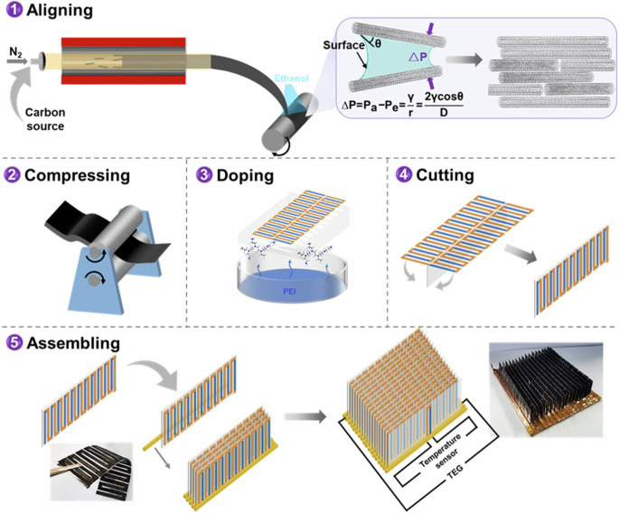
reported a material process approach, containing a developed floating catalyst chemical vapor deposition (FCCVD) with capillary compression assistant alignment and a compressing process, to
prepare macroscopic CNT films with highly ordered CNT assemblies (Fig. 1). The newly developed process could produce CNT films at large scales, which could shorten the preparation process
of high-quality CNT films as well. The environment-friendly solvent EtOH was used in this work. Besides of the high CNT alignment, the achieved CNT films have a high density and a high
purity (low defects and low level of amorphous carbon), resulting in a high electrical conductivity of 2.17 MS m−1 and subsequently a high p-type \({PF}\) of 9.31 mW m−1 K−2. After being
n-type doped with a vapor doping method, the CNT film exhibited a high n-type \({PF}\) of 6.75 mW m−1 K−2. The obtained n-type \({PF}\) is the highest value ever achieved for any n-type CNT
materials, which is even higher than that of state-of-the-art n-type inorganic TE materials at room temperature. The reason for the high n-type \({PF}\) is mainly attributed to the aligned
CNTs in the film, which allow the vapor of n-type dopant to permeate deeply inside the film for efficient n-type doping, leading to the suitable position between the \({E}_{f}\) and the 1D
van Hove singularity for high \(S\) of the CNT films. It is also attributed to the high electrical conductivity of 2.94 MS m−1 derived from the CNT alignment by the capillary compression as
well as the compressing process for high-density CNT films. As the obtained high-performance CNT films were anisotropic, the computational assistant design was used to fabricate the
high-power density curl-able TE generator, which exhibited a high value of 110 W m−2 (560.2 μW m−1 K−2) among flexible (CNT-based) TE devices. A new concept of an intelligent temperature
controller (ITC) with a light-emitting diode (LED) alarm was fabricated with integrated cooling and alarming functions together in one device for automated temperature control. The results
provide a promising way for high _PF_ and high _k_ CNT films, demonstrating the potential of them in the applications of the automated thermal management of electronic devices, which is
different from the use of CNTs in traditional TE cooling applications. RESULTS AND DISCUSSION We used a developed FCCVD method to synthesize the CNT films. Different from previous
literature8,15, anhydrous ethanol was sprayed at a speed of 3 ml min−1 continuously on the CNT aerogel when it was collected on the roller (Fig. 1), named CNT-e films. CNT films without
ethanol treatment (CNT-o) were also synthesized for comparison. High-resolution transmission electron microscopy (TEM) images showed that the majority of the CNTs were multi-walled CNTs, as
shown in Fig. S1. Then, the CNT-e and CNT-o films were further compressed at a pressure of about 100 MPa to improve the packing density of CNTs for higher electrical conductivity as
suggested in the literature8,33. Detailed information was described in the supporting information. Scanning electron microscopy (SEM) and Raman spectroscopy were performed to characterize
the CNT alignment in the obtained CNT films. SEM images showed that the obtained CNTs were aligned along the direction that was parallel to the rolling direction. Ethanol-treated CNT films
(CNT-e) showed higher alignment than the CNT-o films obviously (Fig. 2a and b). The result was consistent with that obtained from the Raman spectra (Fig. S2) which also showed that both
CNT-e and CNT-o had good quality with a high ratio of 21.6 and18.3 for the intensity of graphic structure/the intensity of defect structure (IG/ID)33,38. The TGA curves of CNT-o films and
CNT-e films are shown in Fig. S3. The reason for the higher alignment in CNT-e films was attributed to the self-assembly of CNTs induced by the capillary action of ethanol. As shown in the
insert image in Fig. 2, the capillary force was derived from the pressure difference (\(\Delta P\)) between the pressure of air (\({P}_{a}\)) and the pressure of ethanol (\({P}_{e}\))
according to the Laplace equation39: $$\varDelta P={P}_{a}-{P}_{e}=\frac{\gamma }{r}=\frac{2\gamma \,\cos \theta }{D}$$ (1) where _γ_ was the ethanol surface tension and \({{\mbox{r}}}\) was
the radius of curvature of the ethanol–air interface. \({{\mbox{D}}}\) was the distance between two CNTs, θ was the contact angle of ethanol on the CNT surface. The capillary force and the
strong van der Waals force would effectively move the CNTs together to near-ideal graphitic spacing40,41. Other alcohol solvents might also show a similar effect on the arrangement of CNTs,
various solvents have been studied in literature to prepare well-arranged CNT fibers34,35, CNT liquid crystals17,36, and CNT films15,37. We further compressed the CNT films at a pressure of
about 100 MPa to improve their electrical properties. The compressing process maintained the good quality and good alignment of CNTs as shown in the Raman spectra (Fig. S4). SEM images
showed that the compressed CNT-e films (CNT-e/c) had higher alignment than the compressed CNT-o films (CNT-e/c) (Fig. S5). Figure 2c shows that the electrical conductivity in the direction
parallel to the rolling direction of CNT-e film (\({\sigma}_{\parallel}\)(CNT-e)) was about 2.5 times higher than the \({\sigma}_{\parallel}\)(CNT-o) of CNT-o films. The schematic of the
anisotropic electrical conductivity measurements for CNT films is shown in Fig. S6. While the Seebeck coefficient in the parallel direction (_S_|| (CNT-e)) was almost the same with _S_||
(CNT-o). The positive Seebeck coefficients indicated both the CNT-e and CNT-o were p-type materials. After compressing, the electrical conductivity of CNT-e/c film in the parallel direction
(_σ_|| (CNT-e/c)) significantly increased by 6.6 times, reaching up to 2.17 MS m−1. The sheet resistance of CNT-e/c films in the parallel direction measured by the van der Pauw method was
consistent with the sheet resistance calculated from the electrical conductivity measured by SBA-458, as shown in Table S1. While the Seebeck coefficient in the parallel direction of CNT-e/c
film (_S_|| (CNT-e/c)) was nearly the same with \({S}_{\parallel }\)(CNT-e). Similarly, the electrical conductivity of CNT-o/c film (_σ_|| (CNT-o/c)) increased with the maintained Seebeck
coefficient (_S_|| (CNT-o/c)). The detailed electrical properties as a function of compressing time for CNT-e/c and CNT-o/c films are shown in Fig. S7. Figure S8 shows the densities of CNT-e
film before and after compressing. The density of CNT-e films was about 0.8 g cm−3, which increased to ~2.1 g cm−3 for CNT-e/c films. The results indicated that the electrical conductivity
was proportional to the density of the CNT films. Similar trend was also observed in previous literature8,33. The different behavior in electrical properties during the compressing process
between CNT-e and CNT-o films was attributed to the anisotropic electrical conductivity and isotropic Seebeck coefficient as suggested in previous literature8,42. The increase of electrical
conductivity with maintained Seebeck coefficients of CNT films after compressing was due to that the physical compressing process only led to the decrease of the voids in the CNT films with
little influence to the chemical environment of CNTs, thus resulting in the decoupling of the electrical conductivity and the Seebeck coefficient8,33,43. Ultraviolet Photoelectron
Spectroscopy was performed with gold as a reference to identify the work function change of CNT-e and CNT-e/c films (Fig. S9). The obtained work function of CNT-e film and CNT-e/c film
exhibited similar values, indicating that the chemical environment of the CNT remained constant (the Fermi energy level is unchanged) before and after compressing. During the compressing
process, the key factor affecting the TE performance was the change in the porosity of the CNT films which has been well-discussed in previous works8,33,43,44. A detailed analysis has been
provided in the supporting information (Fig. S7), where the thickness of the CNT films decreased with the compressing time. For the CNT films with similar porosity, the TE performance would
be independent of the thickness as demonstrated by ref. 45. The thicknesses of the CNT film before compressing in this work were in the range of 12.67 ± 0.25 μm and 5.73 ± 0.21 μm for CNT-o
films and CNT-e films, which were in the range of 1.12 ± 0.05 μm and 0.91 ± 0.03 μm after compressing (Fig. S10). The decoupling of the two TE parameters then led to a high maximum p-type
\({PF}\) in the parallel direction of CNT-e/c films (_PF_|| (CNT-e/c)), up to 9.31 mW m−1 K−2 (Fig. 2d). This high \({PF}\) value was comparable to state-of-the-art CNT-based and
conventional TE materials (Fig. 2e)8,15,33,34,43, which was over two times higher than that of commercially used p-type TE materials Bi2Te3 (~4.5 mW m−1 K−2)11. We calculated the weighted
mobility (µ) of the CNT films according to literature46, which helped us to understand the variation of the electrical properties during the capillary compression-assisted alignment and the
compressing process. The detailed calculation was described in the supporting information. Figure 2f showed that the weighted mobility in the parallel direction (μ||) was in the order of
μ||(CNT-e/c) > μ||(CNT-o/c) > μ||(CNT-e) > μ||(CNT-o). The results indicated that both the alignment and the compressing process benefit the increase of μ|| in the CNT films, thus
leading to the significant improvement of _σ_|| and _PF_||. The TE properties of CNT films in the direction perpendicular to the rolling direction have also been characterized (Fig. S11),
which were lower than those in the parallel direction. The maximum \({\sigma }_{\perp }\) and \({{PF}}_{\perp }\) were only 0.51 MS m−1 and 2.21 mW m−1 K−2, respectively, which were obtained
in CNT-e/c films. We used a vapor treatment method to turn the p-type CNT-e/c and CNT-o/c films into n-type as illustrated in Fig. S12. It was different from the solution doping method by
mixing the dopant with CNTs43,47, which minimized the disturbance by n-type dopants to the aligned CNTs in the films. The detailed doping process was described in the supporting information.
A commercially available n-type dopant, poly(ethylene imine) (PEI), was used in this work to check the proposed concept of the n-type doping method. Figure 3a shows the \({S}_{\parallel
}\)(CNT-e/c) and the _σ_||(CNT-e/c) as a function of the PEI vapor treatment time. After being treated by PEI for 10 min, the \({S}_{\parallel }\)(CNT-e/c-PEI) changed from +64.7 µV K−1 to
−51.7 µV K−1. The negative \({S}_{\parallel }\) demonstrated that the PEI-doped CNT-e/c film becomes n-type. When increasing the treatment time, the \({S}_{\parallel }\)(CNT-e/c-PEI)
decreased, which became −44.6 µV K−1 after the film being treated for 120 min. While the \({\sigma }_{\parallel }\)(CNT-e/c-PEI) increased with the treatment time, which reached up to 3.16
MS m−1 after 120 min. The decrease of the \({S}_{\parallel }\)(CNT-e/c-PEI) and the increase of the \({\sigma }_{\parallel }\)(CNT-e/c-PEI) were attributed to the gradual increase of n-type
carrier concentration with PEI treatment time33,43,47,48. It was interesting to notice that the \({S}_{\parallel }\)(CNT-o/c-PEI) (−38.14 µV K−1 after being treated by PEI for 120 min) in
Fig. 3b was smaller than \({S}_{\parallel }\)(CNT-e/c-PEI) although the above results in Fig. 2c showed that the p-type \({S}_{\parallel }\)(CNT-o/c) and \({S}_{\parallel }\)(CNT-e/c) were
nearly consistent with each other. The reason should be attributed to the different \({E}_{f}\) positions related to the 1D van Hove singularity, caused by different doping levels. Previous
literature demonstrated that shifting the position of the \({E}_{f}\) to the 1D van Hove singularity of CNTs by tuning the doping level could not only lead to different Seebeck coefficients
but also the simultaneous improvement of the Seebeck coefficient and the electrical conductivity of CNT films34,47,48. The different doping levels in CNT-e/c-PEI films and CNT-o/c-PEI films
should be due to the different order parameters of CNTs, which allowed different amounts of PEI vapor to permeate inside the films (Fig. 3c and d). In the CNT-o/c films, the CNT bundles were
packed less ordered, which would prevent PEI vapor from permeating deeply inside the films, thus leading to a low n-type Seebeck coefficient of \({S}_{\parallel }\)(CNT-o/c-PEI) = −38.14 µV
K−1 for the inefficient n-type doping. While the CNT bundles in CNT-e/c films were packed more ordered, which was in favor of the deep permeation of PEI vapor inside the films for efficient
n-type doping with a high n-type Seebeck coefficient of \({S}_{\parallel }\)(CNT-e/c-PEI) = −44.6 µV K−1. The order parameter induced different doping levels has been illustrated in Fig. 3c
and d. Similar to this work, using aligned CNT films as electrodes was demonstrated to be an effective strategy to improve the performance of electrochemical reactions since they were in
favor of the redox ions permeating through the thick CNT electrodes49,50. The \({\sigma }_{\parallel }\)(CNT-o/c-PEI) was 2.85 MS m−1 after being treated by PEI for 120 min (Fig. 3b), which
was also smaller than \({\sigma }_{\parallel }\)(CNT-e/c-PEI). It was mainly attributed to the lower order parameter that leads to lower charge carrier mobility in the CNT-o/c-PEI films. The
maximum weighted mobility of CNT-e/c-PEI films was 1703 cm2 V−1 s−1, which was about 1.3 times higher than that of CNT-o/c-PEI films (Fig. S13 and Table S2). The maximum n-type
\({{PF}}_{\parallel }\) of CNT-e/c-PEI films was achieved to be 6.75 mW m−1 K−2, which was about 1.37 times higher than that of CNT-o/c-PEI films (Fig. 3e). The electrical conductivity, the
Seebeck coefficient and the _PF_ of the front and back sides of the CNT-e/c-PEI films were almost consistent as shown in Fig. S14. The results indicated that the n-type CNT films were
uniformed doped by the PEI vapor. The content of PEI in the CNT film was roughly calculated to be about 10.3% according to the weight variation of CNT-e/c-PEI films between 158-350 °C, as
shown in Fig. S1551,52. The TE properties of PEI-doped CNT films in the perpendicular direction have also been characterized (Fig. S16). The maximum \({\sigma }_{\perp }\) values were in the
order of \({\sigma }_{\perp }\)(CNT-o/c-PEI) > \({\sigma }_{\perp }\)(CNT-e/c-PEI). The maximum \({{PF}}_{\perp }\) values were in the order of \({{PF}}_{\perp }\)(CNT-o/c-PEI) >
\({{PF}}_{\perp }\)(CNT-e/c-PEI). We compared the maximum n-type \({{PF}}_{\parallel }\)(CNT-o/c-PEI) with previous literature (Fig. 3f). The maximum n-type \({{PF}}_{\parallel }\) of 6.75
mW m−1 K−2 for PEI doped CNT-e/c films was the highest value ever achieved for any CNT materials, which was even ~1.5 times higher than that of recently reported state-of-the-art n-type
inorganic Bi2Te3 films (~4.6 mW m−1 K−2)31. Note that the high \({PF}\) (9.31 mW m−1 K−2 for p-type and 6.75 mW m−1 K−2 for n-type) in this work could be achieved in macroscopic samples (36
cm × 12 cm), which was different from the 2D materials that exhibit the high \({PF}\) typically in µm-scale21,22. The scalability of these high-performance CNT films would ease the
fabrication of TE devices for the practical applications. In addition, the alignment and the compressing process also resulted in the enhancement of the thermal conductivity of CNT films in
the parallel direction (\({k}_{\parallel }\)) because the alignment increased the mean free path of phonons43 and the compressing process reduced the thermal insulating voids8,33. The
\({k}_{\parallel }\)(CNT-e/c) and \({k}_{\parallel }\)(CNT-e/c-PEI) for the films with the maximum \({{PF}}_{\parallel }\)(CNT-e/c) and \({{PF}}_{\parallel }\)(CNT-e/c-PEI) were 114.3 W m−1
K−1and 86.23 W m−1 K−1, respectively (Fig. S17 and Table S3). The attempts to detect the out-of-plane thermal conductivity of CNT films failed due to the ultra-thin thickness (~1 μm) of the
prepared CNT films, making their out-of-plane thermal conductivity difficult to measure. Similar results have been reported in the previous literature29,47,48. The in-plane thermal
conductivity in the direction perpendicular to the CNT orientation (_k__⊥_) would be similar to the out-of-plane thermal conductivity (_k__out_), due to the good alignment of the CNTs, as
shown in Fig. S18. The _k__⊥_ values of CNT films are shown in Fig. S17b. Both the high \(k\) and the high \({PF}\) were required in active cooling, which were not easy to be obtained
simultaneously in previous materials. As shown in Fig. 3g, conventional CNT films often had high \(k\) but low \({PF}\), while conventional inorganic materials often had high \({PF}\) but
low \(k\) at 300 K. The \({k}_{{eff}}\) values of the p-type CNT-e/c films and the n-type PEI doped CNT-e/c films were calculated at the given conditions of Δ_T_ = 1 K at 300 K, which were
532.78 W m−1 K−1 and 388.98 W m−1 K−1, respectively. The _κ__eff_ of our CNT films exceeded those of CePd3 and conventional TE materials (Table S4). In the meanwhile, the _ZT_ value
increased by 1.2–2.5 times for the CNT films after compressing and vapor doping as shown in Fig. S19. The reason for the increase of _ZT_ was attributed to the increase of the electrical
conductivity/thermal conductivity ratio since the compressed CNT films had different scattering effects on electrons and phonons due to their different mean free paths. Similar results have
also been obtained in previous works8,33,43. The maximum _ZT_ of the CNT-e/c films was comparable to the state-of-the-art reported CNT films as shown in Table S58,15,29,33,53,54,55. Although
the _ZT_ value of CNT films was not high, the excellent electrical and mechanical properties of CNTs make them promising candidates for flexible TE materials. Research on improving the TE
properties of CNT-based materials was still very attractive recently8,15,24,29,33,38,43,44,45,47,48,56. In the meanwhile, previous literature suggests that _ZT_ should not be the only
parameter to evaluate a TE material. High power factor CNT films were still highly desired to fabricate TEGs with high output power density for the practical applications when the waste heat
was abundant and released freely2,8,24,33,38,43,44. We tested the stability, flexibility, and the mechanical strength of the n-type CNT-e/c-PEI films for practical applications. Previous
work demonstrated that PEI-doped CNT films had great stability at room temperature, which maintained their \(S\) at nearly 100% for even 120 days33. The temperature stability of CNT-e/c-PEI
films at 120 °C was tested here. Figure 3h showed that the \({S}_{\parallel }\)(CNT-e/c-PEI) increased at the very beginning of heating, which was attributed to the increase of efficient
n-type doping at high temperatures as suggested in previous literature56. The \({S}_{\parallel }\)(CNT-e/c-PEI) maintained a high value comparable to/even a little bit larger than its
original value after CNT-e/c-PEI films were heated at 120 °C for 1200 h. For comparison, literature reported highly stable n-type dopants56, 1,5,7-trizazabicyclo[4.4.0]dec-5-ene (TBD),
7-methyl-1,5,7-triazabicyclo[4.4.0] dec-5-ene (Me-TBD) and 1,1,3,3-tetramethylguanidine (TMG), were used to dope CNT-e/c films using the same vapor doping method. The \({S}_{\parallel }\)
and \({\sigma }_{\parallel }\) of these dopants doped CNT-e/c films as a function of vapor treatment time were shown in Fig. S20. The \({S}_{\parallel }\) of TMG doped CNT-e/c films dropped
fast at 120 °C, which turned into p-type after only 24 h. While the \({S}_{\parallel }\) values of TBD and Me-TBD doped CNT-e/c films showed great stability similar with \({S}_{\parallel
}\)(CNT-e/c-PEI) under the same vapor doping conditions. To fully evaluate the performance of the prepared CNT films, we compared the \({\sigma }_{\parallel }\), \({{PF}}_{\parallel }\),
high temperature stability, flexibility, and mechanical strength of both CNT-e/c and CNT-e/c-PEI films with previously reported TE films15,31,33,56. Figures 3i and S21 indicated that both
CNT-e/c and CNT-e/c-PEI films were high-performance multiple functional films, which had not only high basic TE properties, such as \({\sigma }_{\parallel }\) and \({{PF}}_{\parallel }\),
but also excellent flexibility, great mechanical strength, and good temperature stability for practical applications. The strain-stress results were shown in Fig. S22, which indicated that
both CNT-e/c and CNT-e/c-PEI films had high strength values of 1240 MPa and 1123 MPa, respectively, in the parallel direction. The strength values of CNT-e/c and PEI-doped CNT-e/c films in
the perpendicular direction were much lower than that in the parallel direction, which were only 144 MPa and 137 MPa, respectively. Figure S23 showed that the electrical properties of
CNT-e/c and CNT-e/c-PEI films in the parallel direction were nearly constant after being bent 10,000 times. These results showed that CNT-e/c and CNT-e/c-PEI films were promising TE
materials with both high TE properties and high mechanical properties required for potential practical applications. After having the high-performance flexible TE films, a TE generator was
fabricated to demonstrate the heat-to-electricity conversion ability of these films. The shape-property relationship was studied in advance to improve the output power density of TEGs.
Single-piece structure TE device was designed since it would minimize the consumption of the generated power of the internal resistance by reducing electrical contact resistance at the p-n
junction28,32,33. Computational design was performed to assist in the fabrication of the single-piece TE device. Firstly, the polarity of the connection bridge should be the same with the TE
module (matching) which had higher thermal conductivity when assuming the geometry of the p-n modules was the same. As shown in Fig. 4a, the connection bridge might also generate
electricity due to the temperature difference between the cold side of the p- (Tcold-p) and n-type (Tcold-n) modules since the thermal conductivities of the p- and n-type materials were
different. The generated voltage would benefit the TE generator when the voltage direction is agreed with that of the TE generator. Otherwise, it would reduce the performance of the TE
generator. The theoretical calculation was performed with COMSOL finite element simulation to show the influence of different polarity bridges on the output voltage of the TE generator.
Figure 4b shows that the different thermal conductivity of the p- and n-type materials would lead to different temperatures at the cold side of the TE modules, thus generating TE voltage at
the connection bridge. The thermal conductivity difference was \({k}_{\parallel }\)(CNT-e/c)): \({k}_{\parallel }\)(CNT-e/c-PEI) = 1.34 for CNT-e/c and CNT-e/c-PEI films, which would result
in a TE voltage difference of 0.46 mV between the TE generator with polarity matched connection bridge and the TE generator with polarity mismatched connection bridge when the TEGs with one
pair of p-n modules were attached on a heat source with a temperature of 100 °C. The TE voltage difference was not negligible, especially when increasing the number of p-n modules. In the
meanwhile, the larger the thermal conductivity difference was, the higher the temperature difference between the two sides of the connection bridge would be, subsequently leading to a larger
TE voltage difference of the device. Secondly, the width and the length needed to be optimized for high output power density TEGs. As the TE properties of both CNT-e/c and PEI-doped CNT-e/c
films were anisotropic, three types of TEGs have been proposed: parallel structure (the length of TE modules parallel to the rolling direction), perpendicular structure (the length of the
TE modules perpendicular to the rolling direction) and annular structure, as shown in Fig. 4c. Assuming the temperature of the hot source was 100 °C and the environmental temperature was 25
°C, the length and the width of the three types of TE generator were optimized with the filler factor of 0.5 (Fig. S24). Fill factor (\({FF}\)) was defined as: \({FF}={D}/(D+W)\), where
\(D\) was the distance between p- and n-type modules and \(W\) was the width of the TE modules. The maximum output powers, in theory, were in the order of parallel structure (33.7 µW) >
annular structure (20.3 µW) > perpendicular structure (18.8 µW) for a constant D + W of 9 cm (Fig. 4d). The optimized length _x_ width for the parallel structure was 25 mm × 2 mm, which
was 15 mm × 2 mm for the perpendicular structure and annular structure devices. With the optimized width and length, the \({FF}\) was then discussed theoretically. Figure S25 shows that the
output power increases with the increase of \({FF}\). TE generator with the parallel structure (par-TEG) was fabricated. It contained 11 pairs of p-n modules with the length of 25 mm and the
width of 2 mm at an \({FF}\) of 0.5 (Fig. 4e), due to the limitation of lab conditions. The fabricated TE generator had good flexibility with no need for extra metal electrodes which could
be rolled easily into a cylinder (Fig. 4e)32,33. The par-TEG exhibited an open-circuit voltage of 81.5 mV and a short-circuit current of 1.4 mA at a temperature difference of 85 K (Fig. 4f).
The maximum power output of the par-TEG was 29.7 μW when the loading resistance equaled to the inner resistance of 56 Ω. The theoretical open-circuit voltage and the theoretical output
power were calculated as shown in Fig. S26. The open-circuit voltage and maximum power output of the SP-TEG are slightly lower than theoretical values. The power density by weight57 and the
power density by area were calculated with the maximum of 720 μW g−1 and 110 W m−2 at the temperature difference of 85 K (Fig. 4g). For comparison, the TEGs with the perpendicular structure
(per-TEG) and annular structure (ann-TEG) were all fabricated (Fig. 4f). The TE performances of per-TEG and ann-TEG were lower than that of par-TEG as shown in Fig. S27. The maximum power
densities for per-TEG and ann-TEG were 54 W m−2 and 62 W m−2, respectively (Fig. 4h). We compared the power output density of par-TEG with that of the flexible TEGs in the literature. The
maximum power output density was normalized according to the literature30,57,58,59. Figure 4i showed that the normalized power output density was as high as Pmax*L/A = 2.75 W m−1 at a
temperature difference of 85 K, which was above the previously reported values for both organ TEGs. For example, He and Shi et al. reported that the normalized power output density for a
flexible PVDF/Ta4SiTe4 composite film-based TE generator was <0.15 W m−1 58. Lin et al. reported that the normalized power output density for flexible CNTs-Te-PEDOT: PSS composite
film-based TE generator was <0.27 W m−1 57. Shi and Chen et al. reported normalized power output density values of <0.1 W m−1 and <0.3 W m−1 for full-inorganic devices
Ag2S0.5Se0.5/Pt-Rh and Ag2Se0.67S0.33/Pt-Rh, respectively30,59. The results demonstrated the good heat-to-electricity conversion ability of the par-TEG fabricated with the developed high
_PF_ CNT films. The output power stability of the TE generator is shown in Fig. S28. The output power of par-TEG showed good stability in the air at room temperature, which retained nearly
95% of its output power in 30 days. The output power of the par-TEG, which was stored in water, decreased with time. After 30 days, it maintained only 20% of the original value. While the
par-TEG was encapsulated with polyethylene terephthalate (PET) films, it could maintain above 90% of the initial value after being kept under water for over 30 days. Although the prepared
SP-TEG/par was not able to maintain 80% of the original output power after 30 days while being immersed in water directly as reported in the previous literature60, the encapsulated
SP-TEG/par exhibited superior stability of the output power in water. We assembled the par-TEGs into an ITC with an LED alarm as a concept for potential applications in the thermal
management of electronic devices, which integrated the cooling and alarming functions in one device. Figure 5a shows that one double-sided par-TEG contains 22 pairs of p-n modules with a
single-piece structure, which then attached on a PET thin film substrate. The ITC was fabricated by assembling each double-sided par-TEG between two copper strips. Weighting paper with
suitable shape was used to make sure that it was electrically insulating between the copper strips and the double-sided par-TEGs. The ITC contained a total of 16 double-sided par-TEGs, which
were then placed on an electrically heating plate to test the temperature-controlling ability of the ITC (Fig. 5b). The whole testing system was shown in Fig. 5c, which contained a fan, a
power source and a temperature monitor, etc. The ITC could work in three modes, namely low temperature, high temperature, and over-high temperature mode. At low temperature mode, the heat
could dissipate through the ITC for cooling. For example, when the plate was heating at a voltage of 4.5 V, it had a temperature of ~46 °C. After placing the ITC on the heating plate, the
temperature decreased and stabilized at ~37 °C since the heat was dissipated through the ITC due to the good thermal conductivity of the CNT modules (Fig. 5d). At high temperatures when the
plate was heating at a voltage of 6 V, the heating plate was ~61 °C without ITC. After placing the ITC on the heating plate, although the temperature decreased to ~48 °C, it was still higher
than the setting temperature of 37 °C (Fig. 5e). Then, the ITC provided an increased output voltage as a signal to turn on the fan for forced heat dissipation at the wind flow rate of 2 m
s−1. Therefore, the temperature decreased to ~35 °C. Figure 5f, g, and h show the infrared images of the heating plate without ITC, the heating plate with ITC, and the heat plate with ITC
plus the forced heat dissipation by a fan. For over-high temperatures, when a voltage of 22 V was supplied to the heating plate, the temperature would increase to ~260 °C. The temperature
was as high as ~145 °C with the ITC, which was higher than the alarm temperature. Then, the ITC turned the LED on. The results demonstrated the potential applications of high-performance CNT
films in intelligent temperature controlling and alarming for the thermal management of electronic devices. The CNT film-based TEG was used as a heat sink for passive cooling at a low
temperature to save energy, which was different from traditional applications of TEGs in active TE cooling that required power supply all the time. It was also used as a power generator to
support an LED temperature alarm at a high temperature to avoid overheating. The high power factor of the CNT films was important for the TEG to generate sufficient output power over the
limited contact area of the heat source to support the LEDs for alarming because the output power density of the TEG was proportional to the power factor of CNT films7,33,43. A new concept
of an ITC with an LED alarm was intentionally proposed, instead of the active TE cooling device, which would extend the application range of the CNT films with a high power factor and a high
thermal conductivity in the thermal management of electronic devices. Macroscopic CNT films with an outstanding n-type power factor of 6.75 mW m−1 K−2 were synthesized with a material
process approach, containing a developed floating catalyst chemical vapor deposition method with capillary compression assistant alignment and a compressing process. The obtained n-type
power factor is the highest value ever achieved for any n-type CNT materials, which is even higher than that of state-of-the-art n-type inorganic TE materials at room temperature31. The
reason for the high n-type power factor was attributed to the high electrical conductivity of 2.94 MS m−1 derived from CNT alignment by the capillary compression as well as the compressing
process. It was also attributed to the high Seebeck coefficient due to aligned CNTs in the film, allowing the vapor of the n-type dopant to permeate deeply inside the film for efficient
n-type doping. Besides of the high TE properties, the macroscopic CNT films also had excellent flexibility, great mechanical strength, and good high-temperature stability (120 °C) for
practical applications. The computational assistant design was used to fabricate the high-power density curl-able TE generator since the high-performance CNT films were anisotropic. It
exhibited a high normalized power output density of 2.75 W m−1 at a temperature difference of 85 K, which was higher than that of previously reported flexible all-inorganic TEGs (<0.3 W
m−1)30,57,58,59. An ITC was fabricated by assembling these TEGs, which exhibited automated temperature-controlling ability. The outstanding power factor and excellent mechanical properties
make these macroscopic CNT films strong candidate for the automated thermal management of electronic devices, which requires a large TE power factor and a large thermal conductivity
simultaneously. METHODS MATERIALS Ethanol was purchased from Tianjin Fuyu Fine Chemical Co., Ltd., China. Thiophene and ferrocene were obtained from Meryer Chemical Technology Co., Ltd.,
China. Methanol and n-hexane were purchased from Tianjin Zhiyuan Chemical Co., Ltd., China. Polyethyleneimine (PEI) (99 %) was purchased from Macklin Co., Ltd., China.
1,5,7-trizazabicyclo[4.4.0]dec-5-ene (TBD) was purchased from Tianjin Heowns Biochemical Technology Co., Ltd., China. 7-methyl-1,5,7-triazabicyclo[4.4.0] dec-5-ene (Me-TBD) was purchased
from Bide Pharmatech Co., Ltd., China 1,1,3,3-tetramethylguanidine (TMG) was purchased from Meryer Chemical Technology Co., Ltd., China. All the chemicals were used without further
purification. PREPARATION OF CNT FILM MWCNT was synthesized in a commercial tube furnace (GSL-1700X) at 1500 °C. The precursor solution was made by dissolving the ferrocene catalyst in a
mixture of n-hexane, methanol, and thiophene. The solution was injected into the reactor at a rate of 1–2 ml min−1 and then carried into the high-temperature zone by N2 at a flow rate of
0.5–1 L min−1. The reaction occurred at normal atmospheric pressure. The produced CNT aerogel was driven out by nitrogen and collected at the tube outlet by a roller with a rotational speed
of about 6 mm s−1. The absolute ethanol was uniformly sprayed at 3 ml min−1 during CNT collection to orient the CNTs by self-assembly (CNT-e). MWCNT FILM DENSIFYING A commercial rolling
pressing machine (Kejing MSK-2150 China) was used to densify MWCNT films. Two rollers rotated synchronously but in opposite directions. A constant pressure force of ~100 MPa was applied
during the compression process. DOPING METHOD The vapor doping was performed by attaching the CNT films (10 mm × 30 mm × 0.9 μm) on the upper side of a glass-made cylindrical sublimation
chamber (40 mm diameter, 70 mm height, Yangzhou Sunflower Glass Instrument Factory). At the same time, a certain amount (0.2 g) of n-type dopants (PEI, Me-TBD, TBD, or TMG) was placed on the
bottom of the cylindrical sublimation chamber. The chamber was heated on a hot plate with a sand bath and without a magnetic stirrer at 120 °C under ambient pressure. Therefore, dopant
molecules are deposited on the CNT film surface after a certain time of heating (from 10 min to 120 min, Fig. 3, Figs. S16 and S20). After finishing doping, the samples were left to cool
down to room temperature naturally in the air. The scheme of the vapor doping process is shown in Fig. S29. THE FINITE ELEMENT ANALYSIS FOR CALCULATING THE PERFORMANCES OF TEG The heat
transfer in solids and electric currents modules in COMSOL Multiphysics was used to calculate the TE performance of TEGs to optimize the structural design of TEGs. The performances of TEG
with the different wide and length of the TE legs as well as the fill factor were simulated by COMSOL Multiphysics simulations. The materials properties used in finite-element analyses are
shown in Table S6. PREPARATION OF TEG AND ITC TEG of parallel structure (par-TEG), perpendicular structure (per-TEG), and annular structure (ann-TEG) with 11 pairs of p-n legs were
fabricated by hand. The length of par-TEG and per-TEG is 90 mm. The length and width of the TE leg for par-TEG are 25 mm and 2 mm, respectively, which are 15 mm and 2 mm, respectively, for
per-TEG. The inner diameter and outer diameter are 14 mm and 29 mm for ann-TEG. The length and width of the TE leg for ann-TEG are 15 mm and 2 mm, respectively. The film of CNT was sealed by
polyethylene terephthalate (PET) films with a patterned structure, and then the CNT film was treated with PEI vapor. After 30 min doping with 0.2 g PEI at 120 °C, the exposed CNT film was
converted from p-type into n-type. After cutting, par-TEG, per-TEG, and ann-TEG were obtained. An ITC was assembled with 16 pieces of double-sided par-TEG and a temperature sensor of a pair
of p-n TE legs. The double-sided par-TEG was attached on a PET thin film substrate (0.2 × 25 × 90 mm). The ITC was fabricated by assembling each double-sided par-TEG between two copper
strips (3 × 5 × 12 mm) with adhesive tape. Weighting paper with suitable shape was used to make sure that it was electrically insulating between the copper strips and the double-sided
par-TEGs. The par-TEG is connected in series by silver paste. CHARACTERIZATION The electrical conductivity and Seebeck coefficient of samples were measured under Ar protection by using
commercial equipment (NETZSCH, SBA-458, Germany). A four-point probe method is designed for the electrical conductivity measurement in the machine. A highly sensitive temperature probe and
temperature control system are used with a temperature stability of ± 0.02 K as claimed by the equipment supplier. The measurement errors for the electrical conductivity and the Seebeck
coefficient are well-controlled to be 5% and 3%, respectively. The thermal conductivity was measured by using commercial equipment (NETZSCH, LFA 467, Germany) as well. The measurement error
of the thermal conductivity is less than 2% as claimed by the equipment supplier. For each data point, three or more samples were tested to get the real properties of the samples. The error
(E) was calculated according to the following equation: $$E=\sqrt{{\sum}_{i=1}^{n}{({X}_{i}-{X}_{m})}^{2}/n}\;{{{{{\rm{and}}}}}}\;{X}_{m}={{\sum}_{i=1}^{n}}{X}_{i}/n$$ where \({X}_{i}\) and
_n_ are experimental data and the number of samples, respectively. Scanning electron microscope images were obtained by using FEI Sirion 200. Raman spectra were recorded by a Laser Raman
Spectrometer (Thermo Fisher, USA) with an excitation wavelength of 532 nm. The output voltage and output power of devices were measured with a Keithley 2400 Multimeter (Keithley Instruments
Inc., USA). DATA AVAILABILITY The authors declare that the data supporting the findings of this study are available within the paper and its supplementary information files. Source data are
provided with this paper. REFERENCES * Bell, L. E. Cooling, heating, generating power, and recovering waste heat with thermoelectric systems. _Science_ 321, 1457–1461 (2008). Article ADS
CAS PubMed Google Scholar * Wang, H. & Yu, C. Organic thermoelectrics: materials preparation, performance optimization, and device integration. _Joule_ 3, 53–80 (2019). Article CAS
Google Scholar * Wei, T.-R. et al. Exceptional plasticity in the bulk single-crystalline van der Waals semiconductor InSe. _Science_ 369, 542–545 (2020). Article ADS CAS PubMed Google
Scholar * Zheng, Y. et al. Defect engineering in thermoelectric materials: what have we learned? _Chem. Soc. Rev._ 50, 9022–9054 (2021). Article ADS CAS PubMed Google Scholar * Hung,
N. T., Hasdeo, E. H., Nugraha, A. R. T., Dresselhaus, M. S. & Saito, R. Quantum effects in the thermoelectric power factor of low-dimensional semiconductors. _Phys. Rev. Lett._ 117,
036602 (2016). Article ADS PubMed Google Scholar * Liu, W., Kim, H. S., Jie, Q. & Ren, Z. Importance of high power factor in thermoelectric materials for power generation
application: a perspective. _Scr. Mater._ 111, 3–9 (2016). Article CAS Google Scholar * El Oualid, S. et al. High power density thermoelectric generators with skutterudites. _Adv. Energy
Mater._ 11, 2100580 (2021). Article CAS Google Scholar * Sun, X. et al. Anisotropic electrical conductivity and isotropic Seebeck coefficient feature induced high thermoelectric power
factor >1800 µW m−1 K−2 in MWCNT Films. _Adv. Funct. Mater._ 32, 2203080 (2022). Article CAS Google Scholar * Zhao, D. & Tan, G. A review of thermoelectric cooling: materials,
modeling and applications. _Appl Therm. Eng._ 66, 15–24 (2014). Article ADS CAS Google Scholar * Tan, S. O. & Demirel, H. Performance and cooling efficiency of thermoelectric modules
on server central processing unit and Northbridge. _Comput. Electr. Eng._ 46, 46–55 (2015). Article Google Scholar * Poudel, B. et al. High-thermoelectric performance of nanostructured
bismuth antimony telluride bulk alloys. _Science_ 320, 634–638 (2008). Article ADS CAS PubMed Google Scholar * Tripathi, A., Lee, Y., Lee, S. & Woo, H. Y. Recent advances in n-type
organic thermoelectric materials, dopants, and doping strategies. _J. Mater. Chem. C._ 10, 6114–6140 (2022). Article CAS Google Scholar * Wang, J. et al. Recent developments of n-type
organic thermoelectric materials: influence of structure modification on molecule arrangement and solution processing. _ChemSusChem_ 15, e202102420 (2022). Article CAS PubMed Google
Scholar * Gao, W. et al. Macroscopically aligned carbon nanotubes for flexible and high-temperature electronics, optoelectronics, and thermoelectrics. _J. Phys. D._ 53, 063001 (2020).
Article ADS CAS Google Scholar * Wang, H. et al. Acid enhanced zipping effect to densify MWCNT packing for multifunctional MWCNT films with ultra-high electrical conductivity. _Nat.
Commun._ 14, 380 (2023). Article ADS CAS PubMed PubMed Central Google Scholar * Lee, R. S., Kim, H. J., Fischer, J. E., Thess, A. & Smalley, R. E. Conductivity enhancement in
single-walled carbon nanotube bundles doped with K and Br. _Nature_ 388, 255–257 (1997). Article ADS CAS Google Scholar * Behabtu, N. et al. Strong, light, multifunctional fibers of
carbon nanotubes with ultrahigh conductivity. _Science_ 339, 182–186 (2013). Article ADS CAS PubMed Google Scholar * Mahan, G. D. & Sofo, J. O. The best thermoelectric. _Proc. Natl
Acad. Sci. USA_ 93, 7436–7439 (1996). Article ADS CAS PubMed PubMed Central Google Scholar * Hicks, L. D. & Dresselhaus, M. S. Effect of quantum-well structures on the
thermoelectric figure of merit. _Phys. Rev. B_ 47, 12727–12731 (1993). Article ADS CAS Google Scholar * Hicks, L. D. & Dresselhaus, M. S. Thermoelectric figure of merit of a
one-dimensional conductor. _Phys. Rev. B_ 47, 16631–16634 (1993). Article ADS CAS Google Scholar * Duan, J. et al. High thermoelectricpower factor in graphene/hBN devices. _Proc. Natl
Acad. Sci. USA_ 113, 14272–14276 (2016). Article ADS CAS PubMed PubMed Central Google Scholar * Shimizu, S. et al. Giant thermoelectric power factor in ultrathin FeSe superconductor.
_Nat. Commun._ 10, 825 (2019). Article ADS CAS PubMed PubMed Central Google Scholar * Hayashi, D. et al. Thermoelectric properties of single-wall carbon nanotube networks. _Jpn J. Appl
Phys._ 58, 075003 (2019). Article ADS CAS Google Scholar * Blackburn, J. L., Ferguson, A. J., Cho, C. & Grunlan, J. C. Carbon-nanotube-based thermoelectric materials and devices.
_Adv. Mater._ 30, 1704386 (2018). Article Google Scholar * Nakai, Y. et al. Giant Seebeck coefficient in semiconducting single-wall carbon nanotube film. _Appl Phys. Express_ 7, 025103
(2014). Article ADS CAS Google Scholar * Hung, N. T., Nugraha, A. R. T., Hasdeo, E. H., Dresselhaus, M. S. & Saito, R. Diameter dependence of thermoelectric power of semiconducting
carbon nanotubes. _Phys. Rev. B_ 92, 165426 (2015). Article ADS Google Scholar * Avery, A. D. et al. Tailored semiconducting carbon nanotube networks with enhanced thermoelectric
properties. _Nat. Energy_ 1, 16033 (2016). Article ADS CAS Google Scholar * Dai, X. et al. Joint-free single-piece flexible thermoelectric devices with ultrahigh resolution p–n patterns
toward energy harvesting and solid-state cooling. _ACS Energy Lett._ 6, 4355–4364 (2021). Article CAS Google Scholar * Wang, Y. et al. Understanding the solvent effects on polarity
switching and thermoelectric properties changing of solution-processable n-type single-walled carbon nanotube films. _Nano Energy_ 93, 106804 (2022). Article CAS Google Scholar * Liang,
J. et al. Modulation of the morphotropic phase boundary for high-performance ductile thermoelectric materials. _Nat. Commun._ 14, 8442 (2023). Article ADS CAS PubMed PubMed Central
Google Scholar * Lu, Y. et al. Staggered-layer-boosted flexible Bi2Te3 films with high thermoelectric performance. _Nat. Nanotechnol._ 18, 1281–1288 (2023). Article ADS CAS PubMed
Google Scholar * Li, K. et al. All-in-one single-piece flexible solar thermoelectric generator with scissored heat rectifying p-n modules. _Nano Energy_ 93, 106789 (2022). Article CAS
Google Scholar * Li, K. et al. Densification induced decoupling of electrical and thermal properties in free-standing MWCNT films for ultrahigh p- and n-type power factors and enhanced ZT.
_Small_ 19, 2304266 (2023). Article CAS Google Scholar * Komatsu, N. et al. Macroscopic weavable fibers of carbon nanotubes with giant thermoelectric power factor. _Nat. Commun._ 12, 4931
(2021). Article ADS CAS PubMed PubMed Central Google Scholar * Lee, J. et al. Direct spinning and densification method for high-performance carbon nanotube fibers. _Nat. Commun._ 10,
2962 (2019). Article ADS PubMed PubMed Central Google Scholar * Headrick, R. J. et al. Versatile acid solvents for pristine carbon nanotube assembly. _Sci. Adv._ 8, eabm3285 (2022).
Article CAS PubMed PubMed Central Google Scholar * Wan, Y.-J. et al. Ultrathin densified carbon nanotube film with “metal-like” conductivity, superior mechanical strength, and ultrahigh
electromagnetic interference shielding effectiveness. _ACS Nano_ 14, 14134–14145 (2020). Article CAS PubMed Google Scholar * Park, K. T. et al. Highly integrated, wearable
carbon-nanotube-yarn-based thermoelectric generators achieved by selective inkjet-printed chemical doping. _Adv. Energy Mater._ 12, 2200256 (2022). Article CAS Google Scholar * Namatsu,
H., Kurihara, K., Nagase, M., Iwadate, K. & Murase, K. Dimensional limitations of silicon nanolines resulting from pattern distortion due to surface tension of rinse water. _Appl Phys.
Lett._ 66, 2655–2657 (1995). Article ADS CAS Google Scholar * Chakrapani, N., Wei, B., Carrillo, A., Ajayan, P. M. & Kane, R. S. Capillarity-driven assembly of two-dimensional
cellular carbon nanotube foams. _Proc. Natl Acad. Sci. USA_ 101, 4009–4012 (2004). Article ADS CAS PubMed PubMed Central Google Scholar * Futaba, D. N. et al. Shape-engineerable and
highly densely packed single-walled carbon nanotubes and their application as super-capacitor electrodes. _Nat. Mater._ 5, 987–994 (2006). Article ADS CAS PubMed Google Scholar *
Fukuhara, K. et al. Isotropic Seebeck coefficient of aligned single-wall carbon nanotube films. _Appl Phys. Lett._ 113, 243105 (2018). Article ADS Google Scholar * Wang, Y. et al. Green
biopolymer-CNT films exhibit high thermoelectric power factor and electrical conductivity for low temperature heat energy harvesting. _J. Mater. Chem. A_ 10, 25740–25751 (2022). Article CAS
Google Scholar * Dai X., et al. All-automated fabrication of freestanding and scalable photo-thermoelectric devices with high performance. _Adv. Mater_. 36, 2312570 (2024). * MacLeod, B.
A. et al. Large n- and p-type thermoelectric power factors from doped semiconducting single-walled carbon nanotube thin films. _Energy Environ. Sci._ 10, 2168–2179 (2017). Article CAS
Google Scholar * Snyder, G. J. et al. Weighted mobility. _Adv. Mater._ 32, 2001537 (2020). Article CAS Google Scholar * Hu, Q. et al. Double doping approach for unusually stable and
large n-type thermoelectric voltage from p-type multi-walled carbon nanotube mats. _J. Mater. Chem. A_ 8, 13095–13105 (2020). Article CAS Google Scholar * Wang, Y. et al. Mass-produced
metallic multiwalled carbon nanotube hybrids exhibiting high N-type thermoelectric performances. _J. Mater. Chem. A_ 9, 3341–3352 (2021). Article CAS Google Scholar * Im, H. et al.
High-efficiency electrochemical thermal energy harvester using carbon nanotube aerogel sheet electrodes. _Nat. Commun._ 7, 10600 (2016). Article ADS CAS PubMed PubMed Central Google
Scholar * Kuang, Y., Chen, C., Kirsch, D. & Hu, L. Thick electrode batteries: principles, opportunities, and challenges. _Adv. Energy Mater._ 9, 1901457 (2019). Article Google Scholar
* Irani, V., Khosh, A. G., Tavasoli, A. Polyethyleneimine (PEI) functionalized metal oxide nanoparticles recovered from the catalytic converters of spent automotive exhaust systems and
application for CO2 adsorption. _Front. Energy Res._ 8, 196 (2020). * Aghehrochaboki, R., Chaboki, Y. A., Maleknia, S. A., Irani, V. Polyethyleneimine functionalized graphene
oxide/methyldiethanolamine nanofluid: preparation, characterization, and investigation of CO2 absorption. _J. Environ. Chem. Eng._ 7, 103285 (2019). * Chatterjee, K., Negi, A., Kim, K., Liu,
J. & Ghosh, T. K. In-plane thermoelectric properties of flexible and room-temperature-doped carbon nanotube films. _ACS Appl Energy Mater._ 3, 6929–6936 (2020). Article CAS Google
Scholar * Nonoguchi, Y. et al. Simple salt-coordinated n-type nanocarbon materials stable in air. _Adv. Funct. Mater._ 26, 3021–3028 (2016). Article CAS Google Scholar * Zhao, W. et al.
Flexible carbon nanotube papers with improved thermoelectric properties. _Energy Environ. Sci._ 5, 5364–5369 (2012). Article CAS Google Scholar * Horike, S. et al. Bicyclic-ring base
doping induces n-type conduction in carbon nanotubes with outstanding thermal stability in air. _Nat. Commun._ 13, 3517 (2022). Article ADS CAS PubMed PubMed Central Google Scholar *
Liu, C. et al. Role of interfaces in organic–inorganic flexible thermoelectrics. _Nano Energy_ 89, 106380 (2021). Article CAS Google Scholar * Xu, Q. et al. Conformal organic–inorganic
semiconductor composites for flexible thermoelectrics. _Energy Environ. Sci._ 13, 511–518 (2020). Article CAS Google Scholar * Liang, J. et al. Flexible thermoelectrics: from silver
chalcogenides to full-inorganic devices. _Energy Environ. Sci._ 12, 2983–2990 (2019). Article CAS Google Scholar * Hata, S. et al. Green route for fabrication of water-treatable
thermoelectric generators. _Energy Mater. Adv._ 2022, 9854657 (2022). Article ADS Google Scholar Download references ACKNOWLEDGEMENTS H.W. acknowledges financial support from the National
Natural Science Foundation of China (Grant No. 52276014 and 51888103), the Fundamental Research Funds for the Central Universities, and The World-Class Universities (Disciplines). This work
was also supported by the HPC platform and the Instrument Analysis Center, Xi’an Jiaotong University. AUTHOR INFORMATION Author notes * These authors contributed equally: Hong Wang, Kuncai
Li. AUTHORS AND AFFILIATIONS * State Key Laboratory of Multiphase Flow in Power Engineering & Frontier Institute of Science and Technology, Xi’an Jiaotong University, Xi’an, 710054,
China Hong Wang, Kuncai Li, Xin Hao, Jiahao Pan, Tiantian Zhuang, Xu Dai, Jing Wang, Bin Chen & Daotong Chong * School of Energy and Power Engineering, Xi’an Jiaotong University, Xi’an,
710054, China Hong Wang, Xin Hao, Jing Wang, Bin Chen & Daotong Chong Authors * Hong Wang View author publications You can also search for this author inPubMed Google Scholar * Kuncai Li
View author publications You can also search for this author inPubMed Google Scholar * Xin Hao View author publications You can also search for this author inPubMed Google Scholar * Jiahao
Pan View author publications You can also search for this author inPubMed Google Scholar * Tiantian Zhuang View author publications You can also search for this author inPubMed Google
Scholar * Xu Dai View author publications You can also search for this author inPubMed Google Scholar * Jing Wang View author publications You can also search for this author inPubMed Google
Scholar * Bin Chen View author publications You can also search for this author inPubMed Google Scholar * Daotong Chong View author publications You can also search for this author inPubMed
Google Scholar CONTRIBUTIONS H.W. and K.L. contributed to the manuscript equally. H.W. and K.L. conceived and planned the experiments; K.L. carried out the experiments; H.X., J.P., T.Z.,
X.D. and J.W. contributed to sample preparation; H.W. performed the analysis and wrote the manuscript; B.C., D.C., contributed to the interpretation of the results; All authors discussed the
results and commented on the manuscript. CORRESPONDING AUTHOR Correspondence to Hong Wang. ETHICS DECLARATIONS COMPETING INTERESTS The authors declare no competing interests. PEER REVIEW
PEER REVIEW INFORMATION _Nature Communications_ thanks Shinichi Hata and the other anonymous reviewer(s) for their contribution to the peer review of this work. A peer review file is
available. ADDITIONAL INFORMATION PUBLISHER’S NOTE Springer Nature remains neutral with regard to jurisdictional claims in published maps and institutional affiliations. SUPPLEMENTARY
INFORMATION SUPPLEMENTARY INFORMATION PEER REVIEW FILE SOURCE DATA SOURCE DATA RIGHTS AND PERMISSIONS OPEN ACCESS This article is licensed under a Creative Commons Attribution 4.0
International License, which permits use, sharing, adaptation, distribution and reproduction in any medium or format, as long as you give appropriate credit to the original author(s) and the
source, provide a link to the Creative Commons licence, and indicate if changes were made. The images or other third party material in this article are included in the article’s Creative
Commons licence, unless indicated otherwise in a credit line to the material. If material is not included in the article’s Creative Commons licence and your intended use is not permitted by
statutory regulation or exceeds the permitted use, you will need to obtain permission directly from the copyright holder. To view a copy of this licence, visit
http://creativecommons.org/licenses/by/4.0/. Reprints and permissions ABOUT THIS ARTICLE CITE THIS ARTICLE Wang, H., Li, K., Hao, X. _et al._ Capillary compression induced outstanding n-type
thermoelectric power factor in CNT films towards intelligent temperature controller. _Nat Commun_ 15, 5617 (2024). https://doi.org/10.1038/s41467-024-50057-x Download citation * Received:
11 February 2024 * Accepted: 28 June 2024 * Published: 04 July 2024 * DOI: https://doi.org/10.1038/s41467-024-50057-x SHARE THIS ARTICLE Anyone you share the following link with will be able
to read this content: Get shareable link Sorry, a shareable link is not currently available for this article. Copy to clipboard Provided by the Springer Nature SharedIt content-sharing
initiative