- Select a language for the TTS:
- UK English Female
- UK English Male
- US English Female
- US English Male
- Australian Female
- Australian Male
- Language selected: (auto detect) - EN
Play all audios:
ABSTRACT Photoelectrochemical seawater splitting is a promising route for direct utilization of solar energy and abundant seawater resources for H2 production. However, the complex salinity
composition in seawater results in intractable challenges for photoelectrodes. This paper describes the fabrication of a bilayer stack consisting of stainless steel and TiO2 as a cocatalyst
and protective layer for Si photoanode. The chromium-incorporated NiFe (oxy)hydroxide converted from stainless steel film serves as a protective cocatalyst for efficient oxygen evolution and
retarding the adsorption of corrosive ions from seawater, while the TiO2 is capable of avoiding the plasma damage of the surface layer of Si photoanode during the sputtering of stainless
steel catalysts. By implementing this approach, the TiO2 layer effectively shields the vulnerable semiconductor photoelectrode from the harsh plasma sputtering conditions in stainless steel
coating, preventing surface damages. Finally, the Si photoanode with the bilayer stack inhibits the adsorption of chloride and realizes 167 h stability in chloride-containing alkaline
electrolytes. Furthermore, this photoanode also demonstrates stable performance under alkaline natural seawater for over 50 h with an applied bias photon-to-current efficiency of 2.62%.
SIMILAR CONTENT BEING VIEWED BY OTHERS PT NANOCLUSTERS ON GAN NANOWIRES FOR SOLAR-ASSSISTED SEAWATER HYDROGEN EVOLUTION Article Open access 12 January 2023 PHOTOTHERMAL-ENABLED SINGLE-ATOM
CATALYSTS FOR HIGH-EFFICIENCY HYDROGEN PEROXIDE PHOTOSYNTHESIS FROM NATURAL SEAWATER Article Open access 29 April 2023 PHOTOTHERMAL-PROMOTED ANION EXCHANGE MEMBRANE SEAWATER ELECTROLYSIS ON
A NICKEL-MOLYBDENUM-BASED CATALYST Article Open access 31 March 2025 INTRODUCTION Photoelectrochemical (PEC) water splitting utilizes photoelectrical components to convert sustainable solar
energy into hydrogen, which alleviates the reliance on non-renewable fossil fuels1. Purified water is usually used to prepare electrolytes for PEC water splitting in the laboratory and
commercial water electrolyzers, whereas a large proportion of the global population is still in shortage of drinking water. In contrast, seawater, which occupies around 96.5% of earth’s
water, is a desirable and widespread natural resource for water electrolysis. Currently, the main routes to produce hydrogen from seawater include indirect and direct seawater splitting.
Although indirect seawater splitting, such as traditional water electrolysis coupled with seawater reverse osmosis (SWRO), integrates several mature technology, it also increases the
expenditure and the complexity of the system. While the latter approach is economically more feasible for current technology2, from a long term perspective of view, direct seawater splitting
coupled with solar or wind energy may avoid the cost and complexity of seawater purification process, which is suitable for application scenarios where space is limited such as offshore
platforms or ships3. Compared with direct seawater electrolysis conducted through electrolyzers powered by photovoltaic systems, PEC seawater splitting could utilize solar energy directly
without additional micro-grids or AC-DC devices, which may further simplify the process of H2 production from seawater. In terms of photocatalysis seawater splitting, although some
researchers recently investigated that indium gallium nitride photocatalyst achieved solar to hydrogen efficiency of 6.2% in a large-scale photocatalytic water-splitting system, this
technology also faces several challenges, such as gas separation of H2 and O2 and precious metal photocatalyst.” However, the complicated salinity in seawater presents a severe obstacle to
the stable operation of photoelectrodes as well as entire photoelectrolytic cells2. PEC seawater splitting is confronted with complex challenges, such as chloride oxidations, corrosion,
precipitation, membrane fouling, etc4,5,6. Compared with photocathodes, photoanodes face more intractable problems derived from corrosion and the competition between chloride oxidation and
oxygen evolution reaction (OER)7. Thus, cocatalysts or protective layers are needed between the photoanode and electrolyte for anticorrosion purposes to enable stable PEC seawater splitting
operations8,9. For instance, the MoO3 layer, constructed with surface doping engineering, served as the barrier layer for corrosive ions, while dual-doping of B and Mo on BiVO4 enhanced the
utilization efficiency of photogenerated holes and achieved the highest HClO production in seawater splitting10. However, chlorine is corrosive and difficult to store and transport, which
makes it a less desirable product on the anode. To suppress chloride oxidation, the alkaline condition is preferable because the cocatalysts can reveal the 480 mV overpotential superiority,
inhibiting chlorine chemistry11. Nevertheless, the present design of cocatalysts or protective layers on photoanodes are still under intensive research for higher stability and overall
hydrogen production rate. Significant progress in saline water electrolysis has been reported, with several novel anode structures for anticorrosion, including the Cl– blocking layer12 as
well as the polyatomic anion-rich catalysts13. These protective configurations have also been proven to be effective on photoanodes for the PEC system. For instance, efficient catalysts in
seawater electrolysis, including MnO_x_14, cobalt phosphate15, NiFeO_x_16, and RhO217, have been investigated on PEC seawater splitting and acquired remarkable performances. Recently,
stainless steels have been studied as non-noble electrocatalysts for water splitting on account of high-activity transition metals and remarkable conductivity18,19,20. Although stainless
steel has presented its potential performance towards water electrolysis and anticorrosion, its application as the protective cocatalyst on photoelectrodes in PEC systems is still restricted
by the incompatible preparation methods with semiconductor based photoelectrodes, as well as the resultant interfacial defects, and its parasitic light absorption. The loading of
cocatalysts on photoelectrodes in PEC systems is more challenging compared with electrolysis systems because the semiconductor substrates are more vulnerable to the surface and interfacial
damages during the introduction of cocatalysts, which may generate interfacial defects that result in the recombination of photogenerated minority carriers21,22. Thin film deposition
techniques, such as physical vapor deposition, are effective and convenient methods for preparing cocatalysts for photoelectrodes. In comparison with bulk alloy, stainless steel thin films
produced by sputtering are prone to form finer grain size and amorphous structure, which results in intensive pitting resistance23. However, the plasma damage derived from sputtering cannot
be ignored for semiconductor substrates. The ion flux in the plasma exerts a negative effect on effective minority carrier lifetime for silicon heterojunction solar cells24. In addition, the
compositions of the films may vary from bulk stainless steel targets, owning to preferential sputtering of elements25. Furthermore, another intractable drawback associated with stainless
steel films is the dilemma between the suitable thickness for chloride resistance and optical loss26. Therefore, great efforts are needed to overcome the plasma damage on the interface due
to sputtering and optical loss because of opaque stainless steel films to achieve remarkable PEC performance in seawater splitting. This paper describes the design and fabrication of a
bilayer stack composed of stainless steel and titanium dioxide (TiO2), serving as the catalytic and protective layer for Si photoanode, which achieves PEC seawater splitting performance. The
compact stainless steel top layer presents effective anticorrosion in seawater and efficient OER catalytic ability, while the TiO2 bottom layer effectively prevents the defect states from
plasma damage during sputtering of stainless steel. In consequence, this back-illuminated Si photoanode achieves a 3.65% applied bias photon-to-current efficiency (ABPE) and a long-term
stability of about 167 h under chloride-containing alkaline electrolytes. The measured H2 production rate of cathode in this PEC system reaches up to 600 μmol h−1 cm−2 in alkaline natural
seawater, which stands out among previous photoanodes operating in seawater splitting. RESULTS CONSTRUCTION OF SILICON PHOTOANODE WITH STAINLESS STEEL AND TIO2 STACK AS A PROTECTIVE
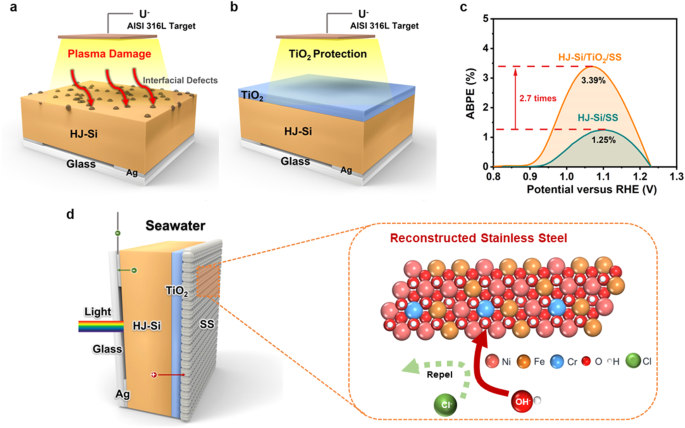
COCATALYST LAYER The Si photoanode (Supplementary Fig. 1) was fabricated by depositing TiO2 and stainless steel films on a heterojunction Si substrate
(ITO/n+-a-Si/a-Si/c-n-Si/a-Si/p+-a-Si/ITO, denoted as HJ-Si). The TiO2 layer was deposited by atomic layer deposition (ALD) with an optimized thickness of 10 nm. Stainless steel films
(denoted as SS) were fabricated by direct current (DC) magnetron sputtering with an AISI 316 L target (Figs. 1a and 1b). In comparison with HJ-Si/SS, TiO2 passivated photoanode
(HJ-Si/TiO2/SS) presents a higher photocurrent density with a much steeper increase (Supplementary Fig. 2), which renders an ABPE of 3.39% for HJ-Si/TiO2/SS, 2.7 times that of HJ-Si/SS (ABPE
1.25%, Fig. 1c). The improved PEC performance could be attributed to the fact that TiO2 effectively passivates the defects on the ITO layer of HJ-Si induced from the plasma damage as well
as the Fermi level pinning at the metal/semiconductor interface27,28. The thickness of TiO2 presents no significant effect on the stability of Si photoanode when its thickness exceeds 8 nm,
while thicker TiO2 might pose a threat to the conductivity of photoelectrode. Thus, considering both the conductivity and protection, the TiO2 layer with 10 nm is selected. Owing to the
protection from TiO2, relatively thick catalytic layers could be sputtered from AISI 316 L and Ni, respectively, with the same thicknesses (20 nm, denoted as SS-20 and Ni-20) to compare the
OER performance (Supplementary Table 1). Meanwhile, thicker SS films (83 and 123 nm) were prepared to further optimize the seawater splitting performance (denoted as SS-83 and SS-123). Upon
electrochemical reconstruction in seawater, the compact SS film transformed into Cr-NiFeOOH as OER cocatalysts and restrained the substrate from electrolytes oxidation and Cl− etching (Fig.
1d). However, according to UV-vis transmission spectra (Supplementary Fig. 3), the light transmittance decreases dramatically with a thicker SS layer, which restricts the photocurrents and
ABPEs of photoanodes. To alleviate this problem, the back-illuminated configuration is adopted to relieve the dilemma between light illumination and cocatalyst loading20,27, inspired by the
profound discusstion25 about the relationship between carrier diffusion length, Si thickness ratio, and photocatalytic performance. The back-illuminated photoanode was constructed from 155
μm thick silicon substrate with an ultra-long carrier diffusion length of 1940 µm22, which ensures abundant light absorption without sacrificing PEC photocurrents. ELECTROCHEMICAL
RECONSTRUCTION OF STAINLESS STEEL DURING ACTIVATION The textured photoanode indicates the compact bilayer stack of TiO2/SS coated on multilayered HJ-Si (Figs. 2a and 2b), as evidenced by
scanning electron microscope (SEM) and cross-sectional transmission electron microscopy (TEM). The property of pristine SS film before the reaction is governed by the sputtering process. The
first concern for preparation is the preferential sputtering of alloy owing to different sputtering yields of different elements, which is determined by the difference of relative atomic
mass, atom surface binding energy distinction, and bombardment-induced Gibbsian segregation of targets23. The SS thin films were dissolved by nitrohydrochloric acid and then analyzed by
inductively coupled plasma-mass spectrometry (ICP-MS), indicating that the main element proportions (Ni, Fe, Cr) in as-prepared films are similar to AISI 316 L target (Supplementary Table
2). Viewed from the top and cross-sectional SEM, SS thin films are constituted by abundant nanoscale atomic clusters, which is consistent with the Stranski–Krastanov growth mechanism
(Supplementary Fig. 4). SEM element mappings reveal uniform signals, illustrating the homogeneous nature of the film (Supplementary Fig. 4). In addition, the cross-sectional TEM of
HJ-Si/TiO2/SS indicates the uniformity of TiO2 and stainless steel layers coated on the HJ-Si substrate (Supplementary Fig. 5). However, the Bragg diffraction peak intensity of the sputtered
thin films in grazing incidence X-ray diffraction decreases (Supplementary Fig. 6), which is significantly different from AISI 316 L target with a representative austenitic structure. As
evidenced by the high resolution cross-sectional TEM, the pristine SS film illustrates nanocrystalline structure with discrete amorphous domains, consistent with the slight Bragg diffraction
peak intensity in GIXRD (Figs. 2c and 2d). The decrease in the crystallinity of sputtered films, even forming amorphous alloy films, can be attributed to the cascade collision mechanism,
breaking the pristine crystalline structure of the target29. As a result, the nanocrystalline or amorphous structure prepared by sputtering has been reported to present intensive pitting
resistance, with fewer dislocations or grain boundaries that preferentially adsorb Cl− to induce the onset of corrosion30. However, the electrochemical reconstruction on the surface of
sputtered stainless steel films occurred during activation, which is an intrinsic and common phenomenon of various OER catalysts based on transition metals18,31. After activation, the
near-surface compositions exhibit a prominent change, with more nickel species migrating to the surface region, as evidenced by X-ray photoelectron spectroscopy (XPS). In addition,
calculated from high-resolution XPS, the sum of Cr and Fe weight proportions on the surface of pristine SS is up to over 90% (Supplementary Table 3), indicating the enrichment of Fe and Cr
oxides on the surface (Figs. 2e and 2g), whereas the Ni species with a low percentage remain at metallic state (Fig. 2f). In contrast, more nickel species migrate to the surface in the
reconstructed SS and the peaks located at 856.0 and 873.6 eV are ascribed to the presence of Ni2+ oxidation state, revealing the complete oxidation of Ni (Fig. 2f)32. With regard to the O 1
s spectrum, two deconvoluted peaks, sited at 531.7 and 529.9 eV, are assigned to O-H and metal-O respectively (Supplementary Fig. 7)33. In addition, SS were peeled off by ethanol solution
with ultrasound-assisted extraction and analyzed by TEM. According to the HRTEM, pristine SS exposes the (111) plane of Fe2O3 and (110) plane of the a-Fe, whereas the activated cocatalyst is
prone to expose the (002) plane of Ni(OH)2 (revised Supplementary Fig. 8). Thus, the sputtering stainless steel film is reconstructed into the chromium-incorporated NiFe (oxy)hydroxide and
the catalytic ability and stability of activated HJ-Si/TiO2/SS are evaluated later. Although the compositions on the surface of sputtered stainless steel films change obviously, the
structure transformation between pristine and activated samples is negligible. As evidenced by cross-sectional TEM (Fig.2b), the thickness of pristine SS is near 78 nm, an approximate value
to which measured by spectroscopic ellipsometer (83 nm, Supplementary Table 1), while the thickness change of SS after reconstruction is inappreciable. Before reconstruction, the
heterojunction Si substrate is covered by dense TiO2 film and the pristine SS film before activation is compact without pin-holes or defects. After reconstruction, there are no pit holes in
the SS layers as well as near the TiO2/SS and Si/TiO2 interfaces, which could be attributed to the nanocrystalline structure with discrete amorphous domains in the SS layer. By contrast, the
materials with high crystallites might trigger high pit hole density between intergrain regions, which results in the contact between alkaline electrolyte and substrate34. RECONSTRUCTED
COCATALYSTS FOR ENHANCED PEC PERFORMANCE UNDER CHLORIDE-CONTAINING ALKALINE ELECTROLYTES The current density-potential (J-V) curves of HJ-Si/TiO2 coated with SS-20, SS-83, SS-123, and Ni-20
were measured in 1 M KOH plus 0.5 M NaCl under simulated AM 1.5 G illumination. The drawing of quartz photoelectrochemical cells is provided (Supplementary Fig. 9). Ni is selected as the
control sample due to its exceptional OER properties. When compared to samples of similar cocatalyst thicknesses (20 nm), SS-20 reveals an onset potential of 0.84 V vs. RHE at 0.1 mA cm−2,
which slightly outperforms Ni-20 (Fig. 3a). The photocurrent density of SS-20 reaches 31.65 mA cm–2 at 1.23 V vs. RHE, approaching the saturation photocurrents. Meanwhile, the ABPE of SS-20
reaches 3.30% at 1.07 V vs. RHE, which surpasses the one coated with Ni (Fig. 3b). The incident photon-to-current efficiency (IPCE) of our device was measured at a potential of 1.5 V vs.
RHE. By integrating the measured IPCE over the standard AM 1.5 G spectrum (ASTM G173-03), a photocurrent density of 32 mA/cm2 could be calculated (Supplementary Fig. 9d), which is very close
to that of 34 mA/cm2 at 1.5 V vs. RHE from the J-V test (Fig. 3a) under AM 1.5 G simulator. The consistency between the two sets of photocurrent density demonstrates the accuracy of our AM
1.5 G simulator in simulating sunlight, ensuring the reliability and accuracy of J-V and IPCE measurements. In addition, the electrochemical impedance spectroscopy (EIS) of different
photoanodes were conducted to investigate the charge carrier transport of photoanodes, indicating that SS-20 and SS-83 efficiently reduce the carrier transfer resistances in the
solid/electrolyte interface (Supplementary Fig. 10). Thus, the PEC performances of HJ-Si/TiO2/SS are superior to HJ-Si/TiO2/Ni owing to the electrochemical reconstruction of stainless steel
thin films. In addition, different stainless steels were tested, including AISI 316 L and AISI 304, which were wide used for anticorrosion purposes (Supplementary Fig. 11). The results
indicate that AISI 316 L and AISI 304 shows similar PEC performance with excellent onset potential and ABPE because these two targets possess similar compositions of Ni, Fe and Cr elements.
According to high resolution XPS, the atomic ratio of Fe and Ni is around 0.4 (Supplementary Table 3), which is close to the optimal surface composition ratio in thin film Ni−Fe oxide
catalysts investigated by Bell35,36. The decreasing proportion of Cr on the surface region is also beneficial for OER because Cr oxides are not regarded as efficient OER catalysts in
comparison with Ni and Fe species. The density functional theory (DFT) calculations were performed to explore the four-step OER mechanism on Ni1_−x−y_Fe_x_Cr_y_(OH)2 and Ni(OH)2, which
further facilitates the understanding of the benefits from electrochemical reconstructed stainless steel. The DFT models of Ni1_−x−y_Fe_x_Cr_y_(OH)2 and Ni(OH)2 were built up and calculation
details are provided in the supplement (Supplementary Fig. 12). The Gibbs free energy of OER intermediates under different potentials was calculated to investigate the rate-limiting step,
which is an important parameter to evaluate the OER catalytic activity (Figs. 3d and 3e). The rate-determining step (RDS) of Ni1_−x−y_Fe_x_Cr_y_(OH)2 and Ni(OH)2 is the deprotonation of the
OOH*. Compared with Ni(OH)2, the reaction energy of RDS over Ni1_−x−y_Fe_x_Cr_y_(OH)2 decreases from 1.82 to 1.32 eV at URHE = 1.23 V (Supplementary Table 4 and Table 5), indicating the
prominent promotion to OER over Ni1_−x−y_Fe_x_Cr_y_(OH)2, which is in good agreement with the excellent onset potential and ABPE of HJ-Si/TiO2/SS in chloride-containing alkaline
electrolytes37. As the SS thicknesses increase from 20 to 83 and finally 123 nm, SS-83 presents the best PEC performance under chloride-containing alkaline electrolytes with an ABPE of
3.65%, whereas there is a noticeable decay in onset potential and ABPE for SS-123 which might result from the increase in sheet resistance of SS-123 (Supplementary Table 6). The ABPE tests
were repeated over four different batches of samples in order to alleviate the experiment errors (Supplementary Fig. 13). The anodic and cathodic products of the best sample,
HJ-Si/TiO2/SS-83, were analyzed by the gas chromatograph in a sealed H-cell with light windows (Supplementary Fig. 14) to calculate the Faradaic Efficiencies (FEs) of O2 and H2. The FE of O2
in SS-83 remains over 96% during 10 h, which represents the apparent inhibition of ClO− production (Fig. 3c). The measured H2 production rate maintains around 600 μmol h−1 cm−2, which is
the twice production rate of O2, indicating the complete utilization of carriers (Fig. 3c). The long-term durability was explored by chronoamperometry at a bias of 1.5 V vs. RHE in 1 M KOH
plus 0.5 M NaCl under simulated AM 1.5 G illumination. The current density of SS-20 remains stable for over 145 h (Fig. 4a). On the contrary, the Ni cocatalyst layer continues to flake off
during a short 5 h period, presenting the corrosion vulnerability of Ni under Cl− environment. Impressively, enhanced stability was achieved from the optimized SS-83, with a photocurrent
drop of only about 10% during 167 h without noticeable peeling off of the cocatalyst (Supplementary Fig. 16). This could be attributed to the fact that thicker stainless steel cocatalyst
completely isolates the semiconductor substrate from the corrosive ions in seawater. By contrast, there might be voids or pit holes in the thinner SS cocatalyst (20 nm), leading to
preferential adsorption of chlorides on the nonuniform regions. According to the surface morphology and J-V characteristics after the stability test, the PEC performance and structure of the
photoanode show negligible changes (Fig. 4a and Supplementary Fig. 15), implying the superior anti-corrosion and catalytic ability of SS-83. After the stability test, iron or chromium
partly dissolve in the electrolyte, while the contents of nickel are stable in the film (Supplementary Table 7). Upon another 168 h stability test with cyclic 8 h illumination followed by 16
h dark (open circuit) to mimic the day-night cycling operation, a stable photocurrent could be obtained by the SS-83 sample with negligible surface morphological changes (SEM images in
Supplementary Fig. 17), indicating the successful isolation between electrolyte and semiconductor substrate. After the stability, iron or chromium partly dissolve in the electrolyte, while
the contents of nickel are stable in the film. The polarization curves illustrate that the corrosion potentials of HJ-Si/TiO2/SS are higher than HJ-Si/TiO2/Ni (Supplementary Fig. 18), which
indicates that sputtered SS offers a thermodynamic superiority over nickel films for anticorrosion. SS-83 illustrates the highest corrosion potential and minimum corrosion current
(Supplementary Table 8), which is consistent to the durability results. The corrosion rate of Ni-20 is more than 3 times higher than SS-20 and SS-83. The DFT calculation also reveals the
adsorption behaviors of chloride ions on Ni1_−x-y_Fe_x_Cr_y_(OH)2 and Ni(OH)2. According to the metal chloride-hydroxide corrosion mechanism and CER reaction pathway, Cl− adsorption
behaviors play an essential role in the competitive reaction on photoanode and cocatalyst stabilities. From the DFT calculation results (Fig. 4b), in comparison to Ni(OH)2, Cl− adsorption on
each site of Ni1_−x−y_Fe_x_Cr_y_(OH)2 is weakened, further inhibiting the first elementary reaction step of corrosion process and CER38,39,40, which is a reasonable explanation for improved
stability of chromium-incorporated NiFe (oxy)hydroxide on Si substrate. In addition, the chromic oxide has been utilized to adjust the local reaction environment of transition metal oxide8,
which effectively increases the local alkalinity and avoids chloride damage, achieving stable direct seawater electrolysis. Thus, the effective OER activity and stability can be attributed
to the TiO2/SS bilayer configuration, which acts as the effective protective layer and reconstructed cocatalyst with appropriate reaction energy for OER and adsorption energy of Cl−.
PHOTOELECTROCHEMICAL PERFORMANCE IN ALKALINE SEAWATER The photoelectrochemical performance of HJ-Si/TiO2/SS-83 was further evaluated in seawater, including alkaline natural seawater from the
BoHai Sea of China and simulated seawater with known compositions, containing Cl−, SO42−, Br−, F−, HCO3−, Sr2+ (Supplementary Table 9). Compared with chloride-containing alkaline
electrolytes, there is an increase of overpotential at 10 mA cm−2 for alkaline natural seawater (near 30 mV) and simulated seawater (near 70 mV) (Fig. 5a). The ABPEs also decrease from 3.32%
for 1 M KOH plus 0.5 M NaCl to 2.62% for alkaline natural seawater (Fig. 5b). However, the O2 Faradaic efficiency still maintains over 95% during the test (Fig. 5c), indicating that the
corrosion of photoanode in natural seawater is not the reason for the reduced performance. Moreover, the duration for stable seawater splitting shrinks to around 55 h (Fig. 5d), due to the
severe salt precipitation on the photoanode from the natural seawater with high salinity (Supplementary Fig. 19). Although the overall performance of HJ-Si/TiO2/SS-83 decreases, the measured
H2 production rate remains around 600 μmol h−1 cm−2 (Fig. 5c and Supplementary Fig. 20) and the calculated total H2 production reaches 741.6 ml cm−2 (Supplementary Table 10). The hydrogen
production rate of various PEC seawater splitting systems is predicted, compared with HJ-Si/TiO2/SS measured through GC, indicating that hydrogen production of Si photoanode with the bilayer
stack is ten times more efficient than other PEC seawater splitting systems, which stands out among previously reported photoanodes on seawater splitting. The natural seawater is
multi-component with a variety of dissolved ions, resulting in competitive reactions for both photoanode and cathode. When the photoelectrodes operate in the simulated seawater without a
buffer solution, the pH around the cathode will increase because of the consumption of H+, which results in the accumulation of insoluble hydroxides of Ca(OH)2 and Mg(OH)2. The addition of
potassium hydroxide into the simulated seawater leads to the precipitation of Ca(OH)2 and Mg(OH)2 prior to the PEC test (Supplementary Fig. 21), thereby preventing the precipitation of the
cathodes. In addition, SO42− has been reported to present a positive effect on stability due to the preferential adsorption of SO42−, which forms the negative charge layer repulsing chloride
ions40. However, apart from the existence of Cl−, other kinds of halide ions, such as Br− and F−, also exist in the seawater, which is evidenced to accelerate catalyst structural
reconstruction and deactivation41. As a result, the reaction environment on the surface of catalysts might further deteriorate due to the synergy of various halide ions, which results in an
apparent decrease in stability. To simplify the complicated salinity in seawater, the influence from chloridion in seawater on semiconductor-based photoanode is investigated in this study,
revealing the anticorrosion mechanism from the reconstructed stainless steel on seawater splitting. But it is of great significance to investigate the corrosion behaviors of photoelectrode
in relation to all ions on seawater splitting in future research. DISCUSSION In summary, this paper describes the design and fabrication of a Si photoanode coated with a TiO2/SS bilayer
stack as protective and catalytic layer for stable PEC seawater splitting. The TiO2 protective layer prevents the ITO layer of HJ-Si from defects induced by plasma damage during sputtering.
Moreover, the chromium-incorporated NiFe (oxy)hydroxide reconstructed from stainless steel is an effective protective cocatalyst for seawater splitting with substantial OER activity
enhancement as well as inhibiting the adsorption of Cl−. The fabricated photoanode achieves stable water splitting in chloride-containing alkaline electrolytes for 167 h. Furthermore,
although the photoanode in simulated seawater shows decreased stability, this PEC system remains stable for 55 h with a recorded H2 production rate (600 μmol h-1 cm-2), a performance that
stands out among existing seawater-based PEC systems for solar H2 production. This design strategy opens a new pathway to accommodate the incompatible anticorrosion properties with reduced
interfacial damages for low-cost stainless steel applied in semiconductor photoelectrodes, which may enable stable H2 production from solar energy using abundant seawater. METHODS
FABRICATION OF SI ELECTRODE AND THE DEPOSITION OF TIO2 n-type c-Si wafers (1-3 Ω·cm resistivity, 155 μm thickness, and (100) orientation) were used as the starting substrate. The c-Si
substrates were etched by a mixture of 5 wt% potassium hydroxide (KOH, Macklin Co., Ltd, 0.95) and 10 wt% isopropyl alcohol (IPA, tianjin real&lead Co., Ltd) for 20 min under 80 °C in
order to produce the pyramid texture. After cleaning by the RCA method (NH4OH/H2O2 aqueous solution, 80 °C), followed by HF etching (5% HF aqueous solution, tianjin kermel Co., Ltd, 60 s) to
remove the native oxide, intrinsic a-Si layers (5 nm) were deposited by plasma-enhanced chemical vapor deposition (PECVD) at 200 °C. Then, highly doped n+-a-Si and p+-a-Si layers were also
prepared by putting into PECVD chamber and depositing at 200 °C. n+-a-Si (5 nm) and p+-a-Si (5 nm) were fabricated next to intrinsic a-Si to form the heterojunction to separate
photogenerated carriers. p-type a-Si was deposited using a gas mixture containing 4% silane diluted in hydrogen and BF3 at 0.9 Torr and 40 W RF power for 200 s. n-type a-Si layer was
deposited at 1.0 Torr, and 40 W RF power for 200 s, using a gas mixture containing 6.7% silane diluted in hydrogen with the PH3:SiH4 doping gas42. A layer of ITO with 80 nm thickness was
prepared on both side of Si substrate by radio frequency (RF) magnetron sputtering (0.2 Pa, 40 W, 4 min, in 20 sccm Ar without heating), to increase the electrical conductivity of the
surfaces while reduce the light reflection. The protective layer TiO2 (10 nm) was prepared by ALD at 150 °C with 300 cycles. The thickness of TiO2 is determined by several factors, including
chemical stability, electrical conductivity, and film uniformity. Considering thicker TiO2 might sacrifice the electrical conductivity, a thickness of 10 nm is selected for the TiO2 layer,
as TiO2 exceeding 8 nm already demonstrates enough protection against plasma damage towards interfaces according to previous studies27. The cycle sequences are as follows: titanium (IV)
isopropoxide (TTIP, Sigma-Aldrich, ≥99.9999%) dosed for 3 s with N2 purging for 8 s later; ultrapure water dosed for 0.2 s with N2 purging for 8 s. THE SPUTTER OF NI AND PT CATALYTIC LAYER
Stainless steel and Ni were deposited respectively through custom-made direct current (DC) magnetron sputtering. AISI 316 L and Ni targets were provided by Zhongnuo Advanced Material
(Beijing) Technology Co., Ltd. To remove the residual gas, the base pressure of the chamber was maintained at 10-5 Pa, and then high purity Ar flow with 20 sccm gas flow was transported into
the system. Finally, the chamber pressure was fixed at 1 Pa. The sputter power was kept at 10 W and sputter durations were adjusted. PREPARATION OF ALKALINE SEAWATER Substitute seawater was
prepared according to Standard Practice for the Preparation of Substitute Ocean Water (An American National Standard, Designation: D 1141–98 (2003)). To prepare the substitute ocean water,
24.534 g sodium chloride (NaCl, Heowns Co., Ltd, 0.99) and 40.94 g anhydrous sodium sulfate (Na2SO4, tianjin real&lead Co., Ltd) were dissolved in 800 mL water. Then Stock Solution No.1
(20 mL) and Stock Solution No. 2 (10 mL) were added with vigorous stirring. Finally, the solution was diluted to 1.0 L. The compositions for preparing Stock Solution No.1 and Stock Solution
No. 2 were shown as follows: Stock Solution No.1: MgCl2·6H2O (Tianjin fengchuan Co., Ltd, 55.56 g), CaCl2(anhydrous) (China National Pharmaceutical Group Co., Ltd, 5.79 g) and SrCl2·6H2O
(Tianjin fuchen Co., Ltd, 0.21 g) were dissolved in 100 mL water; Stock Solution No.2: KCl (Heowns Co., Ltd,, 6.95 g), NaHCO3 (Tianjin fengchuan Co., Ltd, 2.01 g/L), KBr (Energy chemical
Co., Ltd,, 1.0 g), H3BO3 (Aladdin Co., Ltd, 0.27 g/L) and NaF (Aladdin Co., Ltd, 0.03 g/L) were dissolved in 100 mL water. The natural seawater was collected from BoHai Sea in China and
filtered to remove sediment and other solids. The preparation of alkaline seawater was shown as follows: 56.106 g of KOH was added to the 1 L seawater. Then the solution was stranded for 6
hours and filtered to prepare alkaline seawater. PEC MEASUREMENTS Three-electrode configuration was fabricated for PEC measurements which consisted of the reference electrode (Hg/HgO, Gaoss
Union, Co., Ltd), the counter electrode (platinum foil), and the prepared electrode. The potentials measured with Hg/HgO were converted to reversible hydrogen electrode potential using the
Nernst equation: $${{{{{{\rm{E}}}}}}}_{{{{{{\rm{RHE}}}}}}}={{{{{{\rm{E}}}}}}}_{{{{{{\rm{Hg}}}}}}/{{{{{\rm{HgO}}}}}}}+0.059{{{{{\rm{pH}}}}}}+0.098$$ (1) J-V curves were recorded with a scan
rate of 20 mV s-1 under AM 1.5 G solar simulator by an electrochemical workstation without iR-compensation at indoor temperature (25 °C). An AAA-class solar simulator (San-EI Electric Co.,
Ltd., Japan) equipped with a 150 W Xenon lamp and an AM 1.5 filter was used. Before the experiments, a calibrated Si photodiode43,44 (Thorlabs, FDS100-CAL) was used to calibrate the power
intensity of light to 100 mW/cm2. Chronoamperometry was measured in the same system for a long-term stability test. Software Image J was used to measure the active geometric areas of
back-illuminated electrodes. The ABPEs were tested under the three-electrode configuration using the following equation, in which J (mA/cm2) is the photocurrent density from J-V curves, Vb
(vs. RHE) is the corresponding applied bias between the working electrode and the reference electrode, and P represented the incident illumination intensity with a value of 100 mW cm−2
$${{\mbox{ABPE}}}={{\mbox{J}}}\times \frac{1.23{{\mbox{-}}}\left|{{{\mbox{V}}}}_{{{\mbox{b}}}}\right|}{{{\mbox{P}}}}\times 100\%$$ (2) The amount of O2 was measured from gas chromatography
(GC, Agilent 7890B). The amount of ClO– was measured according to N, N-diethyl-p-phenylenediamine sulfate (DPD) spectrophotometric method. The Faradaic efficiency of photoanode products was
calculated as follows: $$ {{{{{\mathrm{Faraday}}}}}} \, {{{{{\mathrm{Efficiency}}}}}}=\\ \frac{{{{{{\mathrm{Moles}}}}}} {{{{{\mathrm{products}}}}}}\times {{{{{\mathrm{Number}}}}}} \,
{{{{{\mathrm{of}}}}}} \, {{{{{\mathrm{transferred}}}}}} \, {{{{{\mathrm{electrons}}}}}}\times {{{{{\mathrm{Faraday}}}}}} \, {{{{{\mathrm{constant}}}}}}}{{{{{{\mathrm{The}}}}}} \,
{{{{{\mathrm{number}}}}}} \, {{{{{\mathrm{of}}}}}} \, {{{{{\mathrm{electrons}}}}}} \, {{{{{\mathrm{passed}}}}}}}\times 100\%$$ (3) The IPCE measuring system (Beijing Zolix, Solar Cell Scan
100) consists of Xenon lamp and monochromator light. Before measurement, the monochromatic light intensity of the system is corrected with a standard silicon solar cell provided with the
IPEC system. The IPCE efficiency calculation formula is shown in the formula, where λ represents the incident light wavelength, Ilight represents the photocurrent density under illumination,
Idark represents the current density under dark field conditions, and P represents the light intensity under the corresponding wavelength43.
$${{\mbox{IPCE}}}=\frac{\left[\frac{1240}{\lambda }\times ({{{\mbox{I}}}}_{{{\mbox{light}}}}-{{{\mbox{I}}}}_{{{\mbox{dark}}}})\right]}{{{\mbox{P}}}}\times 100\%$$ (4) The ingetration of
photocurrent based on the IPCE over standard AM 1.5 G spectrum (ASTM G173-03) is shown as follows44: $${{{\mbox{I}}}}_{{{\mbox{Integrated}}}}={\int }_{\!\!\!\!\lambda=300}^{\lambda
}{{\mbox{q}}}/{{\mbox{hc}}} \, {{\mbox{IPCE}}}\left(\lambda \right)\cdot {{\mbox{E}}}\left(\lambda \right)\cdot \lambda \cdot {{\mbox{d}}}\lambda$$ (5) Where E is the irradiance in W ·
m-2·nm-1, h is the Planck’s constant, c is the light speed. CHARACTERIZATION The morphology was captured by field emission scanning electron microscope (FESEM, Siachi Regulus 8100) and
element mapping was scanned by its energy dispersive spectroscopy. The Grazing incidence X-ray diffraction (GIXRD) (Smartlab) was characterized over a 2θ range from 20° to 80° at a scanning
speed of 2° per step with Cu Kα radiation at 60 kV and 220 mA. The X-ray photoelectron spectroscopy was collected from ESCALAB Xi+ (ThermoFisher Scientific) with an Al Kα X-ray source
(1486.6 eV) and the data were calibrated against the C 1 s photoelectron peak as the reference where binding energy located at 284.8 eV. The optical transmission spectra of the samples were
measured by Shimadzu UV-3600 spectrophotometer. The thickness of TiO2 and sputtered films were measured and fitted through spectroscopic ellipsometer (M-2000 DI, J. A. Woollam Co., Inc.).
DFT CALCULATIONS Density functional theory (DFT) calculations were carried out via Vienna Ab Initio Simulation software (VASP)45. The electron exchange and correlation effects were described
by the Perdew-Burke-Ernzerhof functional (PBE) form of the generalized gradient approximation (GGA)46. Considering van der Waals correction for all systems, the DFT-D3 method with
Becke-Jonson damping was used47. The projector-augmented wave (PAW) method was used to describe the interaction between atomic cores and electrons48. The plane-wave basis set was employed
with a cutoff energy of 400 eV. Meanwhile, the atomic force convergence criterion of force was set to 0.02 eV/Å. The 3-layer surface slab models were chosen for Ni(OH)2 and
Ni1_-x-y_Fe_x_Cr_y_(OH)2. The bottom layer of the above slabs was fixed at bulk structures, and the two top layers and the adsorbates were fully relaxed. A vacuum space with at least 15 Å
was placed in the Z direction. We carefully tested the K-point mesh, and a 3×3×1 k-point grid was selected for all slabs. DFT + U method was employed to better describe the localized 3d
electrons of Ni, Fe, and Cr in Ni(OH)2 and Ni1_-x-y_Fe_x_Cr_y_(OH)_2_, wherein UNi-JNi = 6.4 eV, UFe-JFe = 3.9 eV, and UCr-JCr = 3.5 eV was adopted49. The OER reaction follows the 4-electron
transfer process: $$ \ast+{{{\mbox{OH}}}}^{-}=\ast {{\mbox{OH}}}+{{{\mbox{e}}}}^{-}$$ (6) $$*{{\mbox{OH}}}+{{{\mbox{OH}}}}^{-}=\ast
{{\mbox{O}}}+{{{\mbox{H}}}}_{2}{{\mbox{O}}}+{{{\mbox{e}}}}^{-}$$ (7) $$*{{\mbox{O}}}+{{{\mbox{OH}}}}^{-}=\ast {{\mbox{OOH}}}+{{{\mbox{e}}}}^{-}$$ (8)
$$*{{\mbox{OOH}}}+{{{\mbox{OH}}}}^{-}={{{\mbox{O}}}}_{2}+\ast+{{{\mbox{H}}}}_{2}{{\mbox{O}}}+{{{\mbox{e}}}}^{-}$$ (9) The OER performances were evaluated by calculating the reaction free
energy of each step: $$\Delta {{\mbox{G}}}1
={{\mbox{G}}}(*{{\mbox{OH}}})-{{\mbox{G}}}(*)+\frac{1}{2}{{\mbox{G}}}({{{\mbox{H}}}}_{2})-{{\mbox{G}}}({{{\mbox{H}}}}_{2}{{\mbox{O}}})-{{\mbox{eU}}}-{{\mbox{kT}}}{{{{\mathrm{ln}}}}}\left(\frac{1}{[{{{\mbox{H}}}}^{+}]}\right)
\\ ={{\mbox{G}}}(*{{\mbox{OH}}})-{{\mbox{G}}}(*)+\frac{1}{2}{{\mbox{G}}}({{{\mbox{H}}}}_{2})-{{\mbox{G}}}({{{\mbox{H}}}}_{2}{{\mbox{O}}})-{{\mbox{eU-}}}0.0592{{\mbox{pH}}}$$ (10) $$\Delta
{{\mbox{G}}}2
={{\mbox{G}}}(*{{\mbox{O}}})-{{\mbox{G}}}(*{{\mbox{OH}}})+\frac{1}{2}{{\mbox{G}}}({{{\mbox{H}}}}_{2})-{{\mbox{eU}}}-{{\mbox{kT}}}{{{{\mathrm{ln}}}}}\left(\frac{1}{[{{{\mbox{H}}}}^{+}]}\right)
\\ ={{\mbox{G}}}(*{{\mbox{O}}})-{{\mbox{G}}}(*{{\mbox{OH}}})+\frac{1}{2}{{\mbox{G}}}({{{\mbox{H}}}}_{2})-{{\mbox{eUrhe}}}$$ (11) $$\Delta {{\mbox{G}}}3
={{\mbox{G}}}(*{{\mbox{OOH}}})-{{\mbox{G}}}(*{{\mbox{O}}})+\frac{1}{2}{{\mbox{G}}}({{{\mbox{H}}}}_{2})-{{\mbox{G}}}({{{\mbox{H}}}}_{2}{{\mbox{O}}})-{{\mbox{eU}}}-{{\mbox{kT}}}{{{{\mathrm{ln}}}}}\left(\frac{1}{[{{{\mbox{H}}}}^{+}]}\right)
\\ ={{\mbox{G}}}(*{{\mbox{OOH}}})-{{\mbox{G}}}(*{{\mbox{O}}})+\frac{1}{2}{{\mbox{G}}}({{{\mbox{H}}}}_{2})-{{\mbox{G}}}({{{\mbox{H}}}}_{2}{{\mbox{O}}})-{{\mbox{eU-}}}0.0592{{\mbox{pH}}}$$
(12) $$\Delta {{\mbox{G}}}4
={{\mbox{G}}}({{{\mbox{O}}}}_{2})+{{\mbox{G}}}(*)+\frac{1}{2}{{\mbox{G}}}({{{\mbox{H}}}}_{2})-{{\mbox{G}}}(*{{\mbox{OOH}}})-{{\mbox{eU}}}-{{\mbox{kT}}}{{{{\mathrm{ln}}}}}\left(\frac{1}{[{{{\mbox{H}}}}^{+}]}\right)
\\ ={{\mbox{G}}}({{{\mbox{O}}}}_{2})+{{\mbox{G}}}(*)+\frac{1}{2}{{\mbox{G}}}({{{\mbox{H}}}}_{2})-{{\mbox{G}}}(*{{\mbox{OOH}}})-{{\mbox{eU-}}}0.0592{{\mbox{pH}}}$$ (13) where
\({{\mbox{G}}}(*{{\mbox{OH}}})\), G(*O) and G(*OOH) represent the Gibbs free energy of the intermediates (*OH, *O and *OOH) that is adsorbed on active sites. G(*) is the Gibbs free energy of
a clean slab without any intermediate. G(H2), G(O2) and G(H2O) represent the Gibbs free energy of gas H2, O2 and liquid H2O. The calculation was based on a computational standard hydrogen
electrode model. Metal chloride-hydroxide corrosion mechanisms: $${{\mbox{M}}}+{{{\mbox{Cl}}}}^{-}={{{\mbox{MCl}}}}_{{{\mbox{ads}}}}+{{{\mbox{e}}}}^{-}$$ (14)
$${{{\mbox{MCl}}}}_{{{\mbox{ads}}}}+{{{\mbox{Cl}}}}^{-}={{{\mbox{MCl}}}}_{{{\mbox{x}}}}^{-}+{{{\mbox{e}}}}^{-}$$ (15)
$${{{\mbox{MCl}}}}_{{{\mbox{x}}}}^{-}+{{{\mbox{OH}}}}^{-}={{{\mbox{M}}}({{\mbox{OH}}})}_{{{\mbox{x}}}}+{{{\mbox{e}}}}^{-}$$ (16) In particular, we defined \(\Delta {{\mbox{G}}}\) to show the
adsorption difference of the intermediate on doped Ni_1-x-y_Fe_x_Cr_y_(OH)2 and initial Ni(OH)2. $$\Delta
{{\mbox{G}}}(*{{\mbox{Cl}}})={{{\mbox{G}}}}_{{{{{{{\rm{Ni}}}}}}}_{1-{{{{{\rm{x}}}}}}-{{{{{\rm{y}}}}}}}{{{{{{\rm{Fe}}}}}}}_{{{{{{\rm{x}}}}}}}{{{{{{\rm{Cr}}}}}}}_{{{{{{\rm{y}}}}}}}{({{{{{\rm{OH}}}}}})}_{2}}(*{{\mbox{Cl}}})-{{{\mbox{G}}}}_{{{{{{{\rm{Ni}}}}}}({{{{{\rm{OH}}}}}})}_{2}}(*{{\mbox{Cl}}})$$
(17) where \({{{\mbox{G}}}}_{{{\mbox{Ni}}}1-x-y{{\mbox{Fe}}}x{{\mbox{Cr}}}y({{\mbox{OH}}})_2}(*{{\mbox{Cl}}})\) is the Gibbs free energy of the intermediate on Ni_1-x-y_Fe_x_Cr_y_(OH)2,
\({{{\mbox{G}}}}_{{{\mbox{Ni}}}({{\mbox{OH}}})_2}(*{{\mbox{Cl}}})\) is the Gibbs free energy of the intermediate on initial Ni(OH)2. DATA AVAILABILITY All data generated or analysed during
this study are included in the published article and its Supplementary Information. Source data are provided with this paper. REFERENCES * Wang, T. & Gong, J. Sacrificing Nothing to
Reduce CO2. _Nat. Energy_ 5, 642–643 (2020). Article CAS ADS Google Scholar * Driess, M. et al. Is Direct Seawater Splitting Economically Meaningful? _Energy Environ. Sci._ 14, 3679–3685
(2021). Article Google Scholar * Tong, W. et al. Electrolysis of Low-Grade and Saline Surface Water. _Nat. Energy_ 5, 367–377 (2020). Article CAS ADS Google Scholar * Khan, M. A. et
al. Seawater Electrolysis for Hydrogen Production: A Solution Looking for a Problem? _Energy Environ. Sci._ 14, 4831–4839 (2021). Article CAS Google Scholar * Logan, B. E., Shi, L. &
Rossi, R. Enabling the Use of Seawater for Hydrogen Gas Production in Water Electrolyzers. _Joule_ 5, 760–762 (2021). Article Google Scholar * Veroneau, S. S. & Nocera, D. G.
Continuous Electrochemical Water Splitting from Natural Water Sources via Forward Osmosis. _Proc. Natl Acad. Sci. USA_ 118, e2024855118 (2021). Article CAS PubMed PubMed Central Google
Scholar * Karlsson, R. K. & Cornell, A. Selectivity between Oxygen and Chlorine Evolution in the Chlor-Alkali and Chlorate Processes. _Chem. Rev._ 116, 2982–3028 (2016). Article CAS
PubMed Google Scholar * Guo, J. et al. Direct seawater electrolysis by adjusting the local reaction environment of a catalyst. _Nat. Energy_ 8, 2264–2272 (2023). Google Scholar * Obata,
K. & Takanabe, K. A Permselective CeO_x_ Coating to Improve the Stability of Oxygen Evolution Electrocatalysts. _Angew. Chem. Int. Ed._ 130, 1632–1636 (2018). Article ADS Google
Scholar * Gao, R. T. et al. Ultrastable and High-Performance Seawater-Based Photoelectrolysis System for Solar Hydrogen Generation. _Appl. Catal. B_ 304, 120883 (2022). Article CAS Google
Scholar * Dionigi, F. et al. Design Criteria, Operating Conditions, and Nickel-Iron Hydroxide Catalyst Materials for Selective Seawater Electrolysis. _ChemSusChem_ 9, 962–972 (2016).
Article CAS PubMed Google Scholar * Vos, J. G. et al. MnO_x_/IrO_x_ as Selective Oxygen Evolution Electrocatalyst in Acidic Chloride Solution. _J. Am. Chem. Soc._ 140, 10270–10281
(2018). Article CAS PubMed PubMed Central Google Scholar * Kuang, Y. et al. Solar-Driven, Highly Sustained Splitting of Seawater into Hydrogen and Oxygen Fuels. _Proc. Natl Acad. Sci.
USA._ 116, 6624–6629 (2019). Article CAS PubMed PubMed Central ADS Google Scholar * Okunaka, S., Miseki, Y. & Sayama, K. Functions of MnO_x_ in NaCl Aqueous Solution for Artificial
Photosynthesis. _iScience_ 23, 101540 (2020). Article CAS PubMed PubMed Central ADS Google Scholar * Guan, X. et al. Efficient Unassisted Overall Photocatalytic Seawater Splitting on
GaN-Based Nanowire Arrays. _J. Phys. Chem. C._ 122, 13797–13802 (2018). Article CAS Google Scholar * Kim, J. H. et al. Seawater-Mediated Solar-to-Sodium Conversion by Bismuth Vanadate
Photoanode-Photovoltaic Tandem Cell: Solar Rechargeable Seawater Battery. _iScience_ 19, 232–243 (2019). Article CAS PubMed PubMed Central ADS Google Scholar * Luo, W. et al. Solar
Hydrogen Generation from Seawater with A Modified BiVO4 Photoanode. _Energy Environ. Sci._ 4, 4046–4051 (2011). Article CAS Google Scholar * Schäfer, H. et al. Stainless Steel Made to
Rust: A Robust Water-Splitting Catalyst with Benchmark Characteristics. _Energy Environ. Sci._ 8, 2685–2697 (2015). Article Google Scholar * Schäfer, H. et al. X20CoCrWMo10-9//Co3O4: A
Metal–ceramic Composite with Unique Efficiency Values for Water-splitting in the Neutral Regime. _Energy Environ. Sci._ 9, 2609–2622 (2016). Article Google Scholar * Schäfer, H. &
Chatenet, M. Steel: The Resurrection of a Forgotten Water-Splitting Catalyst. _ACS Energy Lett._ 3, 574–591 (2018). Article Google Scholar * Liu, B. et al. Bifacial Passivation of
n-silicon Metal–Insulator–Semiconductor Photoelectrodes for Efficient Oxygen and Hydrogen Evolution Reactions. _Energy Environ. Sci._ 13, 221–228 (2020). Article CAS Google Scholar * Liu,
B. et al. Double‐Side Si Photoelectrode Enabled by Chemical Passivation for Photoelectrochemical Hydrogen and Oxygen Evolution Reactions. _Adv. Funct. Mater._ 31, 2007222 (2020). Article
Google Scholar * Gupta, R. K. & Birbilis, N. The Influence of Nanocrystalline Structure and Processing Route on Corrosion of Stainless Steel: A review. _Corros. Sci._ 92, 1–15 (2015).
Article CAS Google Scholar * Le AHT et al. Damage to Passivation Contact in Silicon Heterojunction Dolar Cells by ITO Sputtering under Various Plasma Excitation Modes. _Sol. Energy Mater.
Sol. Cells_ 192, 36–43 (2019). Article Google Scholar * Li, T. et al. An Investigation on the Continuous and Uniform Thin Membrane Passive Film Formed on Sputtered Nanocrystalline
Stainless Steel. _Corros. Sci._ 104, 71–83 (2016). Article CAS Google Scholar * Bae, D. et al. Back-Illuminated Si Photocathode: A Combined Experimental and Theoretical Study for
Photocatalytic Hydrogen Evolution. _Energy Environ. Sci._ 8, 650–660 (2015). Article CAS Google Scholar * Hu, S. et al. Amorphous TiO2 Coatings Stabilize Si, GaAs, and GaP Photoanodes for
Efficient Water Oxidation. _Science_ 344, 1005–1009 (2014). Article CAS PubMed ADS Google Scholar * Wang, S. et al. Spatial Decoupling of Light Absorption and Reaction Sites in n-Si
Photocathodes for Solar Water Splitting. _Natl Sci. Rev._ 8, nwaa293 (2021). Article CAS PubMed Google Scholar * Pan, C. et al. Pitting Corrosion of 304SS Nanocrystalline Thin Film.
_Corros. Sci._ 73, 32–43 (2013). Article CAS ADS Google Scholar * Bouzoubaa, A. et al. Insight of DFT and Atomistic Thermodynamics on the Adsorption and Insertion of Halides onto the
Hydroxylated NiO(111) Surface. _Corros. Sci._ 52, 2643–2652 (2010). Article CAS Google Scholar * Ning, M. et al. Boosting Efficient Alkaline Fresh Water and Seawater Electrolysis via
Electrochemical Reconstruction. _Energy Environ. Sci._ 15, 3945–3957 (2022). Article CAS Google Scholar * Li, J. et al. Design of a Multilayered Oxygen‐Evolution Electrode with High
Catalytic Activity and Corrosion Resistance for Saline Water Splitting. _Adv. Funct. Mater._ 31, 2101820 (2021). Article CAS Google Scholar * Zhou, P. et al. Anodized Steel: The Most
Promising Bifunctional Electrocatalyst for Alkaline Water Electrolysis in Industry. _Adv. Funct. Mater._ 32, 2202068 (2022). Article CAS Google Scholar * Yang, J. et al. Efficient and
Sustained Photoelectrochemical Water Oxidation by Cobalt Oxide/Silicon Photoanodes with Nanotextured Interfaces. _J. Am. Chem. Soc._ 136, 6191–6194 (2014). Article CAS PubMed Google
Scholar * Louie, M. W. & Bell, A. T. An Investigation of Thin-Film Ni-Fe Oxide Catalysts for the Electrochemical Evolution of Oxygen. _J. Am. Chem. Soc._ 135, 12329–12337 (2013).
Article CAS PubMed Google Scholar * McCrory, C. C. et al. Benchmarking Heterogeneous Electrocatalysts for the Oxygen Evolution Reaction. _J. Am. Chem. Soc._ 135, 16977–16987 (2013).
Article CAS PubMed Google Scholar * Peugeot, A. et al. Benchmarking of Oxygen Evolution Catalysts on Porous Nickel Supports. _Joule_ 5, 1281–1300 (2021). Article CAS Google Scholar *
Wang, N. et al. Strong-Proton-Adsorption Co-based Electrocatalysts Achieve Active and Stable Neutral Seawater Splitting. _Adv. Mater._ 35, 2210057 (2023). Article CAS Google Scholar * Tu,
Q. et al. Preferential Adsorption of Hydroxide Ions onto Partially Crystalline NiFe-Layered Double Hydroxides Leads to Efficient and Selective OER in Alkaline Seawater. _ACS Appl. Mater.
Interfaces_ 4, 4630–4637 (2021). CAS Google Scholar * Ma, T. et al. The Critical Role of Additive Sulfate for Stable Alkaline Seawater Oxidation on Nickel-Based Electrodes. _Angew. Chem.
Int. Ed._ 60, 22740–22744 (2021). Article CAS Google Scholar * Yuan, T. et al. The Effect of Specific Adsorption of Halide Ions on Electrochemical CO2 Reduction. _Chem. Sci._ 13,
8117–8123 (2022). Article CAS PubMed PubMed Central Google Scholar * Shen, L., Meng, F. & Liu, Z. Roles of the Fermi level of doped a-Si: H and band offsets at a-Si: H/c-Si
interfaces in n-type HIT solar cells. _Sol. Energy_ 97, 168–175 (2013). Article CAS ADS Google Scholar * Boettcher, S. W. et al. Energy-conversion properties of vapor-liquid-solid–grown
silicon wire-array photocathodes. _Science_ 327, 185–187 (2010). Article CAS PubMed ADS Google Scholar * Zhou, X. et al. 570 mV photovoltage, stabilized n-Si/CoOx heterojunction
photoanodes fabricated using atomic layer deposition. _Energy Environ. Sci._ 9, 892–897 (2016). Article CAS Google Scholar * Kresse, G. & Furthmüller, J. Efficiency of Ab-Initio Total
Energy Calculations for Metals and Semiconductors Using a Plane-Wave Basis Set. _Comp. Mater. Sci._ 6, 15–50 (1996). Article CAS Google Scholar * Perdew, J. P., Burke, K. &
Ernzerhof, M. Generalized Gradient Approximation Made Simple. _Phys. Rev. Lett._ 77, 3865–3868 (1996). Article CAS PubMed ADS Google Scholar * Grimme, S., Ehrlich, S. & Goerigk, L.
Effect of the Damping Function in Dispersion Corrected Density Functional Theory. _J. Comput. Chem._ 32, 1456–1465 (2001). Article Google Scholar * Kresse, G. & Joubert, D. From
Ultrasoft Pseudopotentials to the Projector Augmented-Wave Method. _Phys. Rev. B_ 59, 1758–1775 (1999). Article CAS ADS Google Scholar * Wang, L., Maxisch, T. & Ceder, G. Oxidation
Energies of Transition Metal Oxides within the GGA+ U Framework. _Phys. Rev. B_ 73, 195107 (2006). Article ADS Google Scholar * Li, Y. et al. Photoelectrochemical Splitting of Natural
Seawater with α-Fe2O3/WO3 Nanorod Arrays. _Int. J. Hydrog. Energy_ 41, 4096–4105 (2016). Article CAS Google Scholar * Li, F., Dong, B. & Feng, S. Bi Shell-BiOI Core Microspheres
Modified TiO2 Nanotube Arrays Photoanode: Improved Effect of Bi Shell on Photoelectrochemical Hydrogen Evolution in Seawater. _Int. J. Hydrog. Energy_ 44, 29986–29999 (2019). Article CAS
Google Scholar * Yuan, X. et al. Fabrication of Ternary Polyaniline-Graphene Oxide-TiO2 Hybrid Films with Enhanced Activity for Photoelectrocatalytic Hydrogen Production. _Sep. Purif.
Technol._ 193, 358–367 (2018). Article CAS Google Scholar * Liu, J. et al. Facet Engineering of WO3 Arrays toward Highly Efficient and Stable Photoelectrochemical Hydrogen Generation from
Natural Seawater. _Appl. Catal. B_ 264, 118540 (2020). Article CAS Google Scholar * Jadwiszczak et al. Highly Efficient Sunlight‐Driven Seawater Splitting in a Photoelectrochemical Cell
with Chlorine Evolved at Nanostructured WO3 Photoanode and Hydrogen Stored as Hydride within Metallic Cathode. _Adv. Energy Mater._ 10, 1903213 (2020). Article CAS Google Scholar Download
references ACKNOWLEDGEMENTS We acknowledge the National Key R&D Program of China (2021YFA1500804), the National Natural Science Foundation of China (22121004, 22250008, 51861125104, and
22038009), the Program of Introducing Talents of Discipline to Universities (No. BP0618007) and the Xplorer Prize for financial support. AUTHOR INFORMATION AUTHORS AND AFFILIATIONS * School
of Chemical Engineering and Technology; Key Laboratory for Green Chemical Technology of Ministry of Education, Tianjin University, Tianjin, 300072, China Shixuan Zhao, Bin Liu, Kailang Li,
Shujie Wang, Gong Zhang, Zhi-Jian Zhao, Tuo Wang & Jinlong Gong * Collaborative Innovation Center of Chemical Science and Engineering (Tianjin), Tianjin, 300072, China Shixuan Zhao, Bin
Liu, Kailang Li, Shujie Wang, Gong Zhang, Zhi-Jian Zhao, Tuo Wang & Jinlong Gong * Joint School of National University of Singapore and Tianjin University, International Campus of
Tianjin University, Binhai New City, Fuzhou, 350207, China Shujie Wang & Jinlong Gong * Haihe Laboratory of Sustainable Chemical Transformations, Tianjin, 300192, China Zhi-Jian Zhao,
Tuo Wang & Jinlong Gong * National Industry-Education Platform of Energy Storage, Tianjin, 300350, China Zhi-Jian Zhao, Tuo Wang & Jinlong Gong Authors * Shixuan Zhao View author
publications You can also search for this author inPubMed Google Scholar * Bin Liu View author publications You can also search for this author inPubMed Google Scholar * Kailang Li View
author publications You can also search for this author inPubMed Google Scholar * Shujie Wang View author publications You can also search for this author inPubMed Google Scholar * Gong
Zhang View author publications You can also search for this author inPubMed Google Scholar * Zhi-Jian Zhao View author publications You can also search for this author inPubMed Google
Scholar * Tuo Wang View author publications You can also search for this author inPubMed Google Scholar * Jinlong Gong View author publications You can also search for this author inPubMed
Google Scholar CONTRIBUTIONS J.L.G and T.W. supervised the project. J.L.G., T.W. and S.X.Z. conceptualized the project. S.X.Z. and B.L. developed the concept and carried out the experiments
and data analysis. Catalyst synthesis procedures were developed and performed by G.Z. and S.J.W. Theoretical calculations were carried out by Z.J.Z. and K.L.L. All authors discussed the
results and participated in writing of the manuscript. CORRESPONDING AUTHORS Correspondence to Tuo Wang or Jinlong Gong. ETHICS DECLARATIONS COMPETING INTERESTS There are no conflicts to
declare. PEER REVIEW PEER REVIEW INFORMATION _Nature Communications_ thanks the anonymous reviewers for their contribution to the peer review of this work. A peer review file is available.
ADDITIONAL INFORMATION PUBLISHER’S NOTE Springer Nature remains neutral with regard to jurisdictional claims in published maps and institutional affiliations. SUPPLEMENTARY INFORMATION
SUPPLEMENTARY INFORMATION PEER REVIEW FILE SOURCE DATA SOURCE DATA RIGHTS AND PERMISSIONS OPEN ACCESS This article is licensed under a Creative Commons Attribution 4.0 International License,
which permits use, sharing, adaptation, distribution and reproduction in any medium or format, as long as you give appropriate credit to the original author(s) and the source, provide a
link to the Creative Commons licence, and indicate if changes were made. The images or other third party material in this article are included in the article’s Creative Commons licence,
unless indicated otherwise in a credit line to the material. If material is not included in the article’s Creative Commons licence and your intended use is not permitted by statutory
regulation or exceeds the permitted use, you will need to obtain permission directly from the copyright holder. To view a copy of this licence, visit
http://creativecommons.org/licenses/by/4.0/. Reprints and permissions ABOUT THIS ARTICLE CITE THIS ARTICLE Zhao, S., Liu, B., Li, K. _et al._ A silicon photoanode protected with
TiO2/stainless steel bilayer stack for solar seawater splitting. _Nat Commun_ 15, 2970 (2024). https://doi.org/10.1038/s41467-024-47389-z Download citation * Received: 27 September 2023 *
Accepted: 01 April 2024 * Published: 06 April 2024 * DOI: https://doi.org/10.1038/s41467-024-47389-z SHARE THIS ARTICLE Anyone you share the following link with will be able to read this
content: Get shareable link Sorry, a shareable link is not currently available for this article. Copy to clipboard Provided by the Springer Nature SharedIt content-sharing initiative