- Select a language for the TTS:
- UK English Female
- UK English Male
- US English Female
- US English Male
- Australian Female
- Australian Male
- Language selected: (auto detect) - EN
Play all audios:
ABSTRACT Engineering strong metal–support interactions (SMSI) is an effective strategy for tuning structures and performances of supported metal catalysts but induces poor exposure of active
sites. Here, we demonstrate a strong metal–support interaction via a reverse route (SMSIR) by starting from the final morphology of SMSI (fully-encapsulated core–shell structure) to obtain
the intermediate state with desirable exposure of metal sites. Using core–shell nanoparticles (NPs) as a building block, the Pd–FeOx NPs are transformed into a porous yolk–shell structure
along with the formation of SMSIR upon treatment under a reductive atmosphere. The final structure, denoted as Pd–Fe3O4–H, exhibits excellent catalytic performance in semi-hydrogenation of
acetylene with 100% conversion and 85.1% selectivity to ethylene at 80 °C. Detailed electron microscopic and spectroscopic experiments coupled with computational modeling demonstrate that
the compelling performance stems from the SMSIR, favoring the formation of surface hydrogen on Pd instead of hydride. SIMILAR CONTENT BEING VIEWED BY OTHERS MODULATING THE STRONG
METAL-SUPPORT INTERACTION OF SINGLE-ATOM CATALYSTS VIA VICINAL STRUCTURE DECORATION Article Open access 22 July 2022 SYNTHESIS OF CORE@SHELL CATALYSTS GUIDED BY TAMMANN TEMPERATURE Article
Open access 10 January 2024 STRONG METAL–SUPPORT INTERACTIONS ON GOLD NANOPARTICLE CATALYSTS ACHIEVED THROUGH LE CHATELIER’S PRINCIPLE Article 10 May 2021 INTRODUCTION Supported metal
catalysts have long been recognized as the most important group of heterogeneous catalysts for fundamental investigations and modern chemical industries1,2,3,4. Conventionally, these
catalysts are synthesized by anchoring the active metal nanoparticles (NPs) onto certain high-surface-area supports to increase the dispersion of catalytically active sites and stabilize the
metal against leaching5,6,7. Subsequently, the metal–support interface is constructed. Such an interface provides synergistic properties to regulate catalysis by modifying the electronic
(charge transfer between the metal sites and the support) and/or geometric (decoration or coverage of metal sites by the support) parameters, and also by modulating the reaction pathways,
e.g., lattice oxygen in oxide supports may directly participate in catalytic reactions7; multicomponent interfaces can enable tandem reaction pathways that do not exist on single-component
active sites8,9. As a classic prototype in metal–support interactions, the strong metal–support interaction (SMSI) has been defined as the encapsulation of NPs, usually group VIII metals, by
partially reduced oxide supports during high-temperature hydrogen (H2) treatment10,11. Since the very first discovery of SMSI by Tauster et al.12,13,14, SMSI has been widely exploited to
tune catalytic performances of group VIII NPs by engineering geometric and/or electronic structures of these metal sites. For example, the adsorption of H2 or CO on Pd was extremely
suppressed upon the formation of SMSI (refs. 13,15), suggesting that the active metal sites were largely covered by support, which altered the geometric ensembles and improved the thermal
stability of Pd catalysts. Meanwhile, because the reducible oxide support, e.g., TiO2, Co3O4, CeO2, and Nb2O5, is partially reduced to the structure with a nonstoichiometric oxygen
concentration during the reductive annealing, electron transfer between metal NPs and oxide supports was detected16,17,18,19. Under extreme conditions, the formation of intermetallic
structure of the supported metal and metal cations in the supporting oxide was observed20,21. Despite these fascinating interfacial properties in SMSI, the formation of SMSI is restricted to
specific combinations of elements, i.e., group VIII metals with high surface energy and transition metal oxides with low surface energy. Consequently, it is extremely challenging for some
metals, e.g., Au, to manifest SMSI due to their low work function and surface energy15,17,22. Efforts have been devoted in hope of expanding upon the conventional SMSI. One critical element
in this pursuit is switching the high-temperature treatment in H2 into other conditions and thereby changes the mechanistic pathways for the formation of SMSI. For example, Wang et al.
reported SMSI formation between Au NPs and TiO2 induced by melamine under an oxidative atmosphere. With the formation of SMSI, the Au NPs were encapsulated by a permeable TiOx thin layer,
making the Au NPs ultrastable at 800 °C (ref. 23). Xiao et al. reported a wet chemistry approach to construct SMSI in aqueous solution at room temperature, which was realized by engineering
redox interactions between metals and supports. This strategy was applicable to Au, Pt, Pd, and Rh (ref. 15). Christopher et al. developed a strongly bounded-adsorbate-mediated strategy to
construct SMSI between Rh and TiO2 through high-temperature treatment in the mixture of CO2 and H2 (ref. 24). Zhang et al. engineered the SMSI between Au NPs and hydroxyapatite by treating
the Au NP–hydroxyapatite composite in the air at high temperatures17. Although progress has been made in expanding the boundaries of SMSI, one inevitable issue associated with the
conventional SMSI is that upon high-temperature treatment the encapsulation process immediately and uncontrollably takes place, resulting in limited exposure of active sites25. In the ideal
scenario, the oxide coverage on the metal surface needs to be thin and permeable to small molecules, while still fully encapsulating metal NPs to prevent the dissolution, disintegration, and
aggregation of active sites during catalysis. We recently reported that voids and cavity space can be developed in metal–metal oxide core–shell NPs in response to H2 treatment at 200 °C
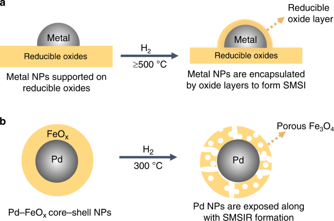
(ref. 26). This observation combined with the current issues in conventional SMSI motivated us to develop alternative routes to metal–support interactions. Here, we denote this type of
structural rearrangement as the strong metal–support interaction via a reverse route (SMSIR). Specifically, we start from the final morphology of SMSI (full encapsulation) and end in the
intermediate state with partial exposure of metal sites (Fig. 1). As a proof of concept, we demonstrate that the core–shell Pd–FeOx NPs can be restructured into a porous yolk–shell structure
after optimized reductive annealing (Pd–Fe3O4–H). Characterizations reveal that Pd atoms gradually migrate into the Fe3O4 lattice and electron is partially transferred from Pd to Fe3O4. The
Pd–Fe3O4–H shows 100% conversion and 85.1% selectivity in the acetylene (C2H2) semi-hydrogenation at atmospheric pressure and a mild reaction temperature of 80 °C. Further investigations
demonstrate that the Pd–Fe3O4–H engineered by the SMSIR alleviates the strong H2 adsorption on Pd sites, in favor of the formation of surface hydrogen (surface-H) instead of hydride during
the hydrogenation of C2H2 to C2H4. Our results on the scenario of engineering SMSIR can help to circumvent the current limits in metal–support interfaces, expanding the boundaries of
conventional SMSI, and providing opportunities to rationally maneuver structure-dependent catalytic outcomes. RESULTS SYNTHESIS AND CHARACTERIZATION Details of the material synthesis can be
found in the “Methods” section. Briefly, the Pd NPs with a size of 5.5 ± 0.5 nm (Supplementary Fig. 1) were prepared by the reduction of palladium (II) acetylacetonate (Pd(acac)2) in
oleylamine (OAM) as modified from a previous report27. The core–shell Pd–FeOx NPs were obtained by a seed-mediated growth method with the pre-made Pd NPs as the seeds and iron (III)
acetylacetonate, as the iron precursor that nucleated on Pd surface, forming an iron oxide shell. The pristine core–shell sample was denoted as Pd-FeOx NPs (Supplementary Figs. 2 and 3). The
SMSIR was constructed by treating the Pd–FeOx NPs at 300 °C in a gas mixture of H2 and argon (Ar; 4 vol.% of H2), and the sample was named as Pd–Fe3O4–H. As a comparison, the Pd–FeOx NPs
were treated in the air at 300 °C to obtain the structure without SMSIR (Pd–Fe3O4–A). X-ray diffraction (XRD) was performed to determine the crystal structures of the samples. As shown in
the XRD patterns of pristine Pd–FeOx and Pd–Fe3O4–A (Supplementary Fig. 4), characteristic peaks at 2_θ_ = 40.1° with very low intensities were detected, which can be assigned to the (111)
peak of face-centered cubic (_fcc_) Pd. No additional peaks in the XRD patterns can be found, indicating the amorphous nature of iron oxide shell in both pristine Pd–FeOx and Pd–Fe3O4–A. On
the contrary, in the XRD pattern of Pd–Fe3O4–H, the intensity of Pd (111) peak increases remarkably, and a series of characteristic peaks at 2_θ_ = 30.6°, 35.9°, 43.5°, 53.9°, 57.3°, 63.0°,
and 74.3° are clearly observed, which can be assigned to (220), (311), (400), (422), (511), (440), and (533) lattices of _γ_-Fe3O4. The XRD characterization indicates that annealing in the
reductive atmosphere may facilitate the spatial redistribution of grains in the oxide shell, and promotes the crystallization of Pd and iron oxides, consistent with our previous report26.
The aberration-corrected high-angle annular dark-field scanning transmission electron microscopy (HAADF-STEM) images of the Pd–Fe3O4–H in Fig. 2a show that the core–shell structure of
pristine Pd–FeOx NPs evolved into a unique porous yolk–shell structure after reductive annealing at 300 °C. Magnified HR-STEM images of Pd–Fe3O4–H in Fig. 2b, c demonstrate a lattice
parameter of 0.217 nm in the core, corresponding to the (111) plane of Pd, and lattice parameters of 0.251 and 0.146 nm in the shell, corresponding to the (311) and (440) planes of Fe3O4.
More interestingly, the magnified HR-STEM image in Fig. 2d shows that there are abundant voids, i.e., lattice vacancies, in the Fe3O4 shells (marked in yellow circles). To analyze the pore
distribution, the pore sizes were determined by averaging pore sizes in multiple HR-STEM images (Supplementary Fig. 5). The majority of these pores on the Fe3O4 shell are micropores with an
average pore size of 0.73 nm. Furthermore, electron energy loss spectroscopy (EELS) mapping of Pd–Fe3O4-H in Fig. 2e–i depict a yolk–shell-like structure of Pd yolk and Fe3O4 shell with
numerous voids. In contrast, for Pd–Fe3O4–A, no significant voids were detected in the Fe3O4 shells and the intact core–shell structure was retained (Supplementary Fig. 6). It is known that
the reducible metal oxides can be partially reduced after high-temperature treatment in H2 (ref. 28). H2 reacts with these oxides to produce water and generate oxygen vacancies in the oxide
matrix. This process can be further facilitated by platinum-group metal NPs supported on those oxides through a H2 spillover process29,30. In the meantime, the crystallization of oxide shell
could promote the rearrangement of atoms, alter the distribution of oxide grains to expand the generated oxygen vacancies, and finally develop voids and cavity space in the structure. XAFS
CHARACTERIZATION AND SIMULATIONS To understand the coordination environments of Pd–Fe3O4 structures, X-ray absorption near-edge spectroscopy (XANES) and extended X-ray absorption fine
structure (EXAFS) were performed (Fig. 3, Supplementary Tables 1 and 2). The chemical states of Pd in Pd–Fe3O4–H and Pd–Fe3O4–A samples were investigated in Pd K-edge EXAFS and XANES, and Pd
foil was employed as a reference (Fig. 3a, b, Supplementary Table 1). The Pd in Pd–Fe3O4–H mainly exists in the form of metallic Pd0, while in Pd–Fe3O4–A, Pd demonstrates an oxidized
feature to some extent. To determine the chemical states and structures of iron oxide shells, the Fe K-edge EXAFS (Fig. 3c), corresponding fitting (Supplementary Table 2), the Fe K-edge
XANES (Fig. 3d), and the Fe K-edge first derivative XANES (Supplementary Fig. 7) were collected and analyzed. Compared with the Fe3O4 and Fe2O3 references, the Fe K-edge XANES and the Fe
K-edge first derivative XANES indicated that the oxide shell in Pd–Fe3O4–H was similar to Fe3O4, while the oxide shell in Pd–Fe3O4–A possessed a partially oxidized Fe3O4 feature (Fig. 3d,
Supplementary Fig. 7). Because Pd–Pd and Pd–Fe bond lengths are similar, it is hard to visualize the difference between these two bonds with Fourier transform results. In this regard, the
wavelet transform (WT) EXAFS as a powerful technique was employed to distinguish these two bonds in our samples. It can be clearly seen from Fig. 4a, b that compared with the standard WT
EXAFS images for Pd–Fe, Pd–O, Pd–Pd, and Pd foil (Supplementary Fig. 8), the Pd in Pd–Fe3O–H remains to be the metallic Pd0 state and Fe–Pd bond emerges (Fig. 4a). In contrast, for the
Pd–Fe3O4–A sample (Fig. 4b), the result demonstrates an oxidized feature with the formation of the Pd–O bond, indicating that the Pd may be slightly oxidized by air, consistent with our
EXAFS and XANES results in Fig. 3. Density functional theory (DFT) simulations combined with the EXAFS curve fitting were carried out to provide more insight into the crystal structure of
iron oxide, and the interactions between Pd and Fe3O4. First, a series of models including a Pd cluster atop the surfaces of Fe2O3 and Fe3O4, and a Pd cluster in oxygen vacancy of Fe2O3, and
Fe3O4 surfaces were constructed and optimized by DFT in Supplementary Fig. 9, and the corresponding FEFF calculated scattering paths were also presented (Supplementary Tables 3–5). Then,
the EXAFS curve fitting on the DFT-optimized structures (Supplementary Figs. 10 and 11, Supplementary Tables 6 and 7) of both Pd K-edge EXAFS and Fe K-edge EXAFS were obtained. It can be
concluded from the results that the best-fitted structure of Pd–Fe3O4–H is that the Pd atoms intercalate into the Fe3O4 matrix (Fig. 4c, detailed optimizing process see Supplementary Fig.
10), indicating that the Pd enters into the Fe3O4 lattice, substituting an oxygen vacancy and tends to form the Fe–Pd bond with Fe in Fe3O4. This observation suggests that there exist strong
interactions between Pd and Fe3O4 in Pd–Fe3O4–H. In contrast, the Pd–Fe3O4–A demonstrated a good match to the local geometry of Pd atoms situated on the surface of Fe3O4 (Fig. 4d, detailed
optimizing process see Supplementary Fig. 11). This result may shed some light on the formation mechanism of this unique porous yolk–shell structure. Evidently, the reaction between H2
molecules and O atoms in the Fe3O4 could generate oxygen vacancies in the structure upon evaporating the produced water. Meanwhile, the crystallization of the oxide shell and the new Fe–Pd
bond formation could promote the rearrangement of oxide lattice and the mobility of Pd atoms, expanding the atom vacancies and developing cavity space in the structure. XPS AND DRIFTS
INVESTIGATIONS To investigate the charge transfer with the formation of SMSIR, X-ray photoelectron spectroscopy (XPS) and CO diffuse reflectance infrared Fourier transform spectroscopy
(DRIFTS) were carried out and shown in Supplementary Figs. 12–14. In the high-resolution Pd 3_d_ XPS of Pd–FeOx NPs, only a Pd 3_d_5/2 peak at 335.4 eV, being assigned to metallic Pd, was
found31,32. When the Pd–FeOx NPs were treated in air at 300 °C, an additional Pd 3_d_5/2 peak at 336.8 eV assigned to PdO, emerged in Supplementary Fig. 12. This observation is consistent
with our XAFS results that the Pd in Pd–Fe3O4–A possesses an oxidized feature to some extent. Furthermore, a Pd 3_d_5/2 shoulder peak at 336.2 eV in the high-resolution Pd 3_d_ XPS of
Pd–Fe3O4–H was detected and assigned to the positively charged Pd (Pdδ+)33, which is originated from intercalation of Pd into Fe3O4 matrix, leading to the strong interactions between Pd and
Fe to form Pd–Fe bond34, in accordance with the XAFS results. Meanwhile, in the high-resolution Fe 2_p_ XPS of Pd–Fe3O4–H (Supplementary Fig. 13), the peaks of Fe 2_p_1/2 and Fe 2_p_3/2
downshifted comparing with that of Pd–Fe3O4–A, further confirming that the charge transfers from Pd to Fe3O4 in Pd–Fe3O4–H. The XPS results indicate the formation of strong interactions and
partial electron transfer between Pd and Fe3O4. The CO DRIFTS was further carried out. During the test, we found that the CO adsorption peak was weak. We, therefore, subtracted the pure
gas-phase signal from each data set. As shown in Supplementary Fig. 14, a peak at ~2153 cm−1 was detected both in the CO DRIFTS of Pd–Fe3O4–H and Pd–Fe3O4–A, which is assigned to Fe3+–CO
(ref. 35). Due to the core–shell morphology of Pd–Fe3O4–A where Pd is fully encapsulated by Fe3O4, no obvious peak was detected in the CO DRIFTS of Pd–Fe3O4–A. In contrast, a very weak peak
at 2102 cm−1 can be seen in the CO DRIFTS of Pd–Fe3O4–H, which is assigned to the linear CO adsorption on metallic Pd (ref. 36). More interestingly, an additional peak at 2134 cm−1 can be
found. Compared with the linear CO adsorption on metallic Pd, this blueshifted peak is assigned to linear CO adsorption on positively charged Pd (CO–Pdδ+)37. Combined with the XPS analysis,
this peak may be attributed to the linear CO adsorption on Pdδ+ in the newly emerged Pd–Fe bond of Pd–Fe3O4–H. The Pd–Fe3O4–H sample was further re-treated in air at 300 °C to obtain the
Pd–Fe3O4–Re sample, and characterized by TEM, CO DRIFTS, and XPS to determine the reversibility of SMSIR. As shown in the TEM image of the Pd–Fe3O4–Re (Supplementary Fig. 15), the sample
still possesses a yolk–shell structure, but the voids are smaller than those of Pd–Fe3O4–H. The XPS of Pd–Fe3O4–Re (Supplementary Fig. 16) demonstrates three Pd states of metallic Pd, Pdδ+
in Pd–Fe bond, and PdO. The intensity of Pdδ+ peak is lower than that of Pd–Fe3O4–H (Supplementary Fig. 12), indicating the decrease of Pdδ+ concentration. The CO DRIFTS of Pd–Fe3O4–Re in
Supplementary Fig. 17 shows that the intensity of CO–Pdδ+ became weaker than that in the CO DRIFTS of Pd–Fe3O4–H in Supplementary Fig. 14, suggesting the CO DRIFTS spectral feature is an
intermediate state between Pd–Fe3O4–H and Pd–Fe3O4–A. The analysis of TEM, CO DRIFTS, and XPS together suggests that the SMSIR in this work is partially reversible. CATALYTIC PERFORMANCE The
semi-hydrogenation of C2H2 to C2H4 is an important reaction in industrial purification of the C2H4 stream produced from naphtha cracking. Pd-based catalysts are mostly used for this
reaction with a consensus that the selectivity is sensitive to the structure of the catalyst38. H2 molecules that are weakly adsorbed onto the Pd surface to form surface-H and C2H2 molecules
that are strongly adsorbed can lead to the production of C2H4, while the formation of hydride usually results in the total hydrogenation to ethane (C2H6). The adsorption of H2 and C2H2
strongly relies on the structure of Pd catalysts. Herein, the hydrogenation of C2H2 was systematically investigated over the prepared catalysts to correlate their structural properties with
the catalytic outcomes. As shown in Fig. 5a, Pd NPs totally converted C2H2 to C2H6 without any selectivity toward C2H4 at 80 °C, while Fe3O4 NPs treated at 300 °C in a gas mixture of H2 and
Ar (4 vol.% of H2; Fe3O4–H) barely demonstrated any catalytic activity for the hydrogenation of C2H2. The selectivity of C2H2 to C2H4 over the Pd–Fe3O4–A was 100%, but the conversion was
only 25.6%. This observation can be mainly attributed to the core–shell structure of the Pd–Fe3O4–A that only exposes limited active Pd sites through the amorphous oxide shell, restricting
the adsorption of the reactants. When the Pd–Fe3O4–H was employed in the semi-hydrogenation of C2H2 at 80 °C, the conversion was 100% and the selectivity was as high as 85.1%. The light-off
curves of Pd–Fe3O4–H (Fig. 5b) demonstrate that the conversion of C2H2 increases with the increment of reaction temperature, while the selectivity toward C2H4 shows the opposite trend. To
comprehensively compare the catalytic performance between the Pd–Fe3O4–H catalyst and previously reported values, the turnover frequency (TOF) was calculated based on the dispersion of Pd
(obtained from H2-pulse chemisorption in Supplementary Table 8). The TOF of Pd–Fe3O4–H was 6.46 s−1, ~100-fold higher than those of a series of state-of-the-art single-atom catalysts at 80
°C (Supplementary Fig. 18), indicating that the Pd–Fe3O4–H demonstrated compelling catalytic performance for semi-hydrogenation of C2H2. Stability tests of the Pd–Fe3O4–H catalyst were
further carried out under both the high and low conversion rates (Fig. 5c, Supplementary Fig. 19). Both results show that the Pd–Fe3O4–H catalyst was remarkably stable in the
semi-hydrogenation of C2H2 to C2H4, which could be originated from the SMSIR between Pd and Fe3O4. The formation of hydride in Pd-based catalysts is temperature-sensitive, and it dominates
the total hydrogenation of C2H2 (refs. 38,39). Hence, the dispersion of Pd is determined by H2-pulse chemisorption (Supplementary Table 8) at various temperatures to examine the formation of
hydride. For the reference Pd NPs (commercial 5 wt.% Pd/Al2O3), the dispersion was determined to be 7.6% at −130 °C (cold bath of isopentane and liquid N2). The corresponding particle size
was calculated to be 14.8 nm. However, H2 uptake on Pd NPs increased significantly at 35 °C, and the estimated particle size decreased to 1.6 nm. This discrepancy can be attributed to the
substantial formation of hydride on Pd NPs at higher temperature that interferes with the estimation of particle size40. In contrast, the Pd–Fe3O4–H sample demonstrated a dispersion of 26.7
and 24.4% at −130 and 35 °C, respectively. The corresponding particle sizes were calculated to be 4.2 and 4.6 nm, in agreement with the Pd core size from STEM investigations (Fig. 2). These
observations indicate that the formation of hydride may be effectively inhibited in our Pd–Fe3O4–H catalyst with SMSIR, leading to a superior selectivity toward semi-hydrogenated products in
the catalytic investigations. CONTROL EXPERIMENTS A series of control samples obtained at different treating temperatures (T200, T300, and T400) were prepared (see “Methods” section) to
determine the optimized condition for the formation of SMSIR. Here, the T300 stands for the Pd–Fe3O4–H sample with SMSIR. The structures and compositions of all catalysts are characterized
by TEM, STEM (Supplementary Figs. 20 and 21), EXAFS, XANES, EXAFS curve fitting on DFT-optimized model (Supplementary Figs. 22–29, Supplementary Tables 9–11), and XRD patterns (Supplementary
Fig. 30). The corresponding structures are summarized here: in the pristine core–shell Pd–FeOx sample, the core and shell were metallic Pd0 and amorphous Fe3O4. When the sample was treated
in the air at high temperature (Pd–Fe3O4–A), the core–shell structures maintained with no obvious formation of voids. When the Pd–FeOx NPs sample was treated in H2 at different temperatures,
the core and shell crystallized into Pd0 and Fe3O4, respectively. As a result, the T200 demonstrated a core–shell structure with fewer voids, T300 (Pd–Fe3O4–H) embraced a yolk–shell-like
structure with numerous voids, and the T400 showed a heterostructure of Fe3O4 islands on Pd NPs. Especially, it can be seen from the EXAFS and corresponding fitting results of T300, i.e.,
Pd–Fe3O4–H, (Fig. 3c, Supplementary Table 2) that compared with the sample obtained at lower annealing temperatures (T200 sample; Supplementary Fig. 24, Supplementary Table 10), the Fe–O
coordination number decreased but Fe–Fe coordination number remained stable in Pd–Fe3O4–H. This result further suggests that in Pd–Fe3O4–H, Pd may substitute the oxygen in iron oxide and
form a new Fe–Pd bond, indicating the formation of strong interactions between Pd NPs and Fe3O4 shell. In addition, Pd–FeOx NPs with different shell thicknesses (STs) were also prepared.
With the increment of STs, the samples were denoted as ST1 NPs, ST2 NPs (i.e., Pd–FeOx NPs), and ST3 NPs, and the NPs were further loaded onto _γ_-Al2O3 to obtain ST1, ST2 (i.e. Pd–Fe3O4–H),
and ST3 (for characterizations see Supplementary Figs. 31–34). To help understand the structures of all prepared samples, a schematic diagram was presented in Supplementary Figs. 35 and 36.
To highlight the role of SMSIR in tuning the conversion and selectivity of C2H2 semi-hydrogenation, both sets of control samples were employed in the C2H2 semi-hydrogenation reaction. As
shown in Supplementary Figs. 37 and 38, the Pd–Fe3O4–H, i.e., T300 and ST2, demonstrates the best catalytic performance. This result further reveals that the optimized ST and treating
condition are essential to the formation of SMSIR for the promoted semi-hydrogenation of C2H2 to C2H4. Based on the structures of the catalysts, the different catalytic outcomes can be
attributed to the following factors: (1) regarding the effect of annealing temperatures, all samples possess a similar Pd size, indicating that the difference of catalytic performance is not
originated from the difference of particle sizes (Supplementary Fig. 39). In the T200 sample, there are fewer voids in the oxide shell and the T200 remains to be a core–shell structure,
resulting in poor exposure of Pd active sites with limited activity. In the case of T400 sample, the core–shell structure is completely destroyed, and therefore the formation of hydrides
turns to be favorable because of the loss of core–shell structural confinement; (2) for the effect of ST, a thicker shell in ST3 makes the Pd active sites less exposed. However, when the
shell becomes too thin as the case in ST1, the structure cannot maintain a fully-encapsulated state, but rather more like a heterostructure with some iron oxide islands on Pd NPs.
Consequently, Pd domains tend to form hydrides due to the lack of core–shell structural confinement effect. REACTION MECHANISM The reaction kinetics were further explored to understand the
underlying mechanisms. As shown in Supplementary Fig. 40, the reaction order over C2H2 is calculated to be −1 (up to 2.5% atm partial pressure), roughly in agreement with Monnier’s work with
~−0.7 reaction order41, indicating the strong adsorption of C2H2 on the surface of Pd in the Pd–Fe3O4–H catalyst. There exists a debate regarding the H2 reaction order. In general, the
reaction order varies from ~0.5 (refs. 42,43), ~1 (refs. 44,45), and up to ~1.6 (ref. 46). In our work, we found the reaction order of H2 to be ~2 (up to 10% atm partial pressure). Such a
positive dependence on H2 partial pressure indicates a much weaker H2 adsorption than previous studies. The temperature dependence of the Pd–Fe3O4–H sample was investigated at 1.2%/6% atm
partial pressure of C2H2/H2 (Supplementary Fig. 41). The apparent activation energy was found to be ~52.7 kJ mol−1, in good agreement with Monnier’s 12.1 kcal mol−1 (ref. 41) and Zhang’s 52
kJ mol−1 (ref. 45). The inelastic neutron scattering (INS) spectra of H2 adsorption on Pd–Fe3O4–H and bulk Pd were presented in Fig. 6. The signal of H2-sorption behavior in Pd–Fe3O4–H is
totally different from that in bulk PdHx. In bulk PdHx sample, an evident signal of hydride was detected, while in Pd–Fe3O4–H, the signal of hydride was very weak47,48. The profile of the
peak at 500 cm−1 reflects the status of the hydride. Specifically, the sharp peak followed by a shoulder as seen in bulk PdHx is due to certain dispersion relation of optical phonons in 3D
space, which results in this particular distribution of phonon states. When hydride is only formed at or near the surface, the 3D network is lacking, leading to the broad bump in the
spectrum of our Pd–Fe3O4–H sample. The result indicates that only surface-H formed during the reaction process, consistent with our H2-chemisorption results. DISCUSSION In this work, we
reported a strategy to engineer the SMSI between Pd and Fe3O4 by using core–shell NPs as a building block through a reverse process of the formation of conventional SMSI, denoted as SMSIR.
With the formation of SMSIR, the core–shell Pd–FeOx NPs was restructured into a unique porous yolk–shell structured Pd–Fe3O4–H, in favor of the exposure of Pd active sites. The Pd–Fe3O4–H
with SMSIR demonstrated excellent catalytic performance in semi-hydrogenation of C2H2 to C2H4 with 100% conversion, 85.1% selectivity, and a high TOF of 6.46 s−1 at the reaction temperature
as low as 80 °C. XAFS investigations along with DFT simulations verified that the Pd atoms intercalate into the Fe3O4 matrix and form strong interactions. The electron transfer was probed by
CO DRIFTS and XPS, suggesting that with the formation of SMSIR, electrons partially transfers from Pd to Fe3O4 shell. The optimized ST of Pd–FeOx NPs and annealing temperature were found to
be essential to the formation of SMSIR. Detailed mechanistic investigations indicated that the SMSIR in Pd–Fe3O4–H alleviates the strong chemisorption of H2 on Pd sites, prevents the
formation of hydride, and consequently leads to a superior selectivity toward C2H4. This work not only develops a high-performance catalyst for semi-hydrogenation of C2H2 but also provides
an approach for the construction of effective catalytic structures based on unconventional SMSI. METHODS CHEMICALS Pd(acac)2 (>99.99%), OAM (90%), tri-n-octylphosphine (TOP, AR.), hexane
(AR.), ethanol (AR.), ferric (III) acetylacetonate (Fe(acac)3, >99.99%), and _γ_-Al2O3 were obtained from Sigma Aldrich Corporate (USA) without further purification. PREPARATION OF 4 NM
PD NPS The Pd NPs were prepared by a modified method from previous work as following27: 70 mg of Pd(acac)2 was mixed with 15 mL of OAM in a 100 mL of four-neck flask under stirring. The
mixture was then heated to 80 °C at a ramping rate of 5 °C min−1 and kept for 1 h under the protection of N2. A total of 0.5 mL of TOP was added to the solution. The mixture was further
heated to 250 °C at a ramping rate of 5.6 °C min−1, and kept at this temperature for another 1 h before cooling down to room temperature. Subsequently, the mixture was transferred to a 50 mL
of centrifuge tube, and 30 mL of ethanol was added. The Pd NPs were separated by centrifugation at 4656 × _g_ for 10 min. Then, the Pd NPs were redispersed in 10 mL of hexane, and
precipitated and washed by adding 30 mL of ethanol for two times. Finally, the Pd NPs were dispersed in 10 mL of hexane for further use. PREPARATION OF PD–FEOX NPS A total of 110 mg of
Fe(acac)3 and 20 mL of OAM were added to a 100 mL four-neck flask. The mixture was heated to 90 °C at a ramping rate of 5 °C min−1 in N2. Subsequently, 12.5 mg of Pd NPs were added, followed
by heating to 250 °C and kept there for 30 min. Afterward, the reaction temperature was raised to 300 °C and kept there for another 30 min before naturally cooling to room temperature.
Then, 30 mL of ethanol was added to precipitate the Pd–FeOx NPs, and then centrifuged at 4656 × _g_ for 10 min. The Pd–FeOx NPs was redispersed in 10 mL of hexane and washed by 30 mL of
ethanol for two times. Finally, the Pd–FeOx NPs were dispersed in 10 mL of hexane. PREPARATION OF FEOX NPS The synthesis of FeOx NPs is the same as the preparation of Pd–FeOx NPs, without
adding Pd NPs. PREPARATION OF SUPPORTED NPS We employed a common-used insert material, _γ_-Al2O3, as the support to anchor the Pd–FeOx NPs (or Fe3O4 NPs, or Pd NPs). Typically, 200 mg of
_γ_-Al2O3 was dispersed in a mixture of 15 mL of hexane and 20 mL of ethanol under sonication. A total of 20 mg of prepared NPs in 5 mL of hexane was added into the solution dropwise under
sonication. The final mixture was further sonicated for 2 h and then magnetically stirred overnight. Subsequently, the NPs/Al2O3 was separated by centrifugation at 6082 × _g_ for 10 min, and
washed by 20 mL of ethanol and hexane for two times. The final sample was dried at 50 °C under vacuum overnight. PREPARATION OF PD–FE3O4–H AND PD–FE3O4–A The Pd–Fe3O4–H sample was prepared
as follows: the Pd–FeOx NPs/Al2O3 (ST2 NPs/Al2O3) was placed in a tube furnace and then heated to 300 °C at a ramping rate of 20 °C min−1 and kept there for 1 h under the atmosphere of 4% H2
in Ar atmosphere. The sample obtained was denoted as Pd–Fe3O4–H. The Pd amount was determined to be 0.171 wt.% by ICP. The Pd–Fe3O4–A sample was prepared by treating the Pd–FeOx NPs/Al2O3
(ST2 NPs/Al2O3) in air under the same reaction condition. PREPARATION OF PD–FE3O4–RE The Pd–Fe3O4–Re sample was prepared by treating Pd–Fe3O4–H in the air for another 1 h. PREPARATION OF
FE3O4–H The Fe3O4–H sample was prepared by the same process of preparation of Pd–Fe3O4–H by using FeOx NPs/Al2O3 instead of Pd–FeOx NPs/Al2O3 . PREPARATION OF CONTROL SAMPLES WITH DIFFERENT
STS Control samples with different ST were obtained by a similar synthesis process of Pd–FeOx NPs using different amounts of Pd NPs seeds (37.5, 12.5, and 6.25 mg), the samples were
respectively denoted as ST1 NPs, ST2 NPs, and ST3 NPs. The NPs were then deposited on the _γ_-Al2O3 and further treated in the atmosphere of 4% H2 in Ar for 1 h according to the same process
of Pd–Fe3O4–H. (ST2 is the Pd–Fe3O4–H sample in this work). PREPARATION OF CONTROL SAMPLES WITH DIFFERENT STRUCTURES The control samples with different structures were prepared according to
a similar process of Pd–Fe3O4–H at different annealing temperatures. The annealing temperature was 200 °C, 300 °C, and 400 °C, and the corresponding samples were denoted as T200, T300, and
T400 (T300 is the Pd–Fe3O4–H sample in this work). CHARACTERIZATION The powder X-ray diffraction (XRD) patterns were collected on a PANalytical X’Pert Pro MPD diffractometer using an
X’Celerator RTMS detector. HAADF-STEM and HR-STEM were performed on a Nion Ultra STEM 100 (operated at 100 kV). EELS spectra were collected on a high-resolution Gatan–Enfina ER with a probe
size of 1.3 Å. TEM and high-angle annular bright-field scanning transmission electron microscopy (HAABF-STEM) were obtained on a Hitachi HD-200 with bright-field STEM detector operating at
200 kV. The dispersion of the Pd was evaluated via pulse H2-Chemisorption with an Altamira Instruments (AMI-300) system. Before the measurements, ~100 mg catalyst was pretreated at 550 °C
for 3 h under 50 sccm of Ar, followed by cooling down to desired temperature (i.e., −130 and 35 °C) under the same flow. Then pulses of 4% H2/Ar from a sample loop with a defined volume
(~0.5 cc) were injected by switching a six-way valve until the eluted peak area of consecutive pulses was constant. The dispersion of Pd was calculated from the volume of H2. INS experiments
were performed at the VISION beamline of the Spallation Neutron Source, Oak Ridge National Laboratory. The Pd–Fe3O4–H sample was first treated under vacuum at 600 °C for 12 h. It was then
loaded in an aluminum sample holder in a helium glovebox. The sample holder was attached to a gas-loading sample stick connected to a gas panel. The blank sample was first measured at −268
°C for 3 h to collect baseline spectrum. H2 gas was then introduced in situ at −238 °C, followed by heating of the sample to −98 °C for reaction. The system was then cooled back to −268 °C
to measure the reacted spectrum. The difference spectrum (reacted minus baseline) shows the signal associated with the hydride species formed during the reaction. The CO DRIFTS results were
obtained on a Nicolet 670 Fourier Transform Infrared Spectrometer with an MCT detector by the following process: each sample (~15 mg) was loaded and then pretreated at 200 °C under Ar for 30
min. Afterward, the sample was cooled down to −120 °C to conduct CO adsorption. When the temperature reached −120 °C, the background was measured and then CO adsorption was conducted for 30
min as followed by desorption with Ar for 10 min (CO desorbed within 1 min after flow Ar). XPS characterization was performed on a PHI VersaProbe III scanning XPS microscope using a
monochromatic Al K-alpha X-ray source (1486.6 eV). XPS spectra were acquired with 200 µm/50 W/15 kV X-ray settings and dual-beam charge neutralization. All binding energies were referenced
to Al 2_p_ peak at 74.8 eV. CATALYTIC PERFORMANCE TESTS The hydrogenation of C2H2 was carried out in a tubular quartz reactor with a 0.25-inch diameter. In a typical run, ~15 mg of catalyst
was mixed with 150 mg of 60–80 mesh quartz sand and placed in the center of the reactor. The catalyst bed was held by quartz wool at both ends and the reactor was loaded in a vertical
furnace (Carbolite Gero). The catalyst was purged with He for 30 min at a flow rate of 20 sccm prior to the reaction under room temperature. Then, the reactor was heated to the desired
temperature (i.e., 30–80 °C), followed by feeding the gas mixture (i.e., 0.6 sccm C2H2, 3 sccm H2 balanced with He) at a total flow rate of 50 sccm. The exit gas mixture was analyzed on-line
by a ThermoStar Mass Spectrometry (Pfeiffer). The conversion and selectivity were calculated by using Eqs. (1) and (2): $$ {{{\rm{C}}_2{\rm{H}}_2}}\;{{\rm{Conversion}}}\left( {\mathrm{\% }}
\right) = \left( {1 - \frac{{{{{\rm{X}}_{{\rm{C}}_2{\rm{H}}_2,{\rm{out}}}}}}}{{{{{\rm{X}}_{{\rm{C}}_2{\rm{H}}_2,{\rm{in}}}}}}}} \right) \times 100{\mathrm{\% }}$$ (1)
$${\mathrm{Selectivity}}\left( {\mathrm{\% }} \right) = \frac{{{{{\rm{X}}_{{\rm{C}}_2{\rm{H}}_4,{\rm{out}}}}}}}{{{{{\rm{X}}_{{\rm{C}}_2{\rm{H}}_2,{\rm{in}}}}} -
{{{\rm{X}}_{{\rm{C}}_2{\rm{H}}_2,{\rm{out}}}}}}} \times 100{\mathrm{\% }}$$ (2) whereas in/out refers to the concentration measured in the inlet/outlet port. Reaction orders with respect to
H2 and C2H2 were calculated by the differential method. The corresponding conversion is maintained below 20% to ensure a true kinetic regime. Apparent activation energy is calculated by the
Arrhenius equation. DFT CALCULATION The density functional theory calculations were performed with the Vienna Ab Initio Simulation Package (VASP)49,50. The on-site Coulomb interaction was
included with the DFT + U method by Dudarev et al.51 in VASP using a Hubbard parameter _U_ = 3.8 eV for the Fe atom. The Perdew–Burke–Ernzerhof52 functional form of generalized-gradient
approximation was used for electron exchange and correlation energies. The projector augmented-wave method was used to describe the electron–core interaction49,53. A kinetic energy cutoff of
450 eV was used for the plane waves. A 3 × 2 × 1 sampling of Brillouin zone using a Monkhorst-Pack scheme was used54. A vacuum layer of 15 Å was added for the surface slabs along the
_z_-direction; the slab contains a total of four layers, with the bottom two layers fixed in their bulk positions. XAFS DATA COLLECTION AND PROCESSING Approximately 20 mg of sample was
enclosed in a nylon washer of 4.953 nm inner diameter and sealed on one side with transparent “Scotch” tape. The sample was pressed by hand to form a uniform pallet, then sealed on the open
side with a tape. XAFS investigation were performed at beamline 10ID-B of the Advanced Photon Source at Argonne National laboratory55. Spectra were collected at the iron K-edge (7112 eV) and
palladium K-edge (24,350 eV) in transmission mode, with an iron and palladium foil as a reference for energy calibration, respectively. All spectra were collected at room temperature and
ten scans were collected for each sample. All data were processed and analyzed using the Athena and Artemis program of the IFFEFFIT package56 based on FEFF 6.0. Reference foil data were
aligned to the first zero-crossing of the second derivative of the normalized _μ_(E) data, which was subsequently calibrated to the literature E0 for each Fe K-edge and Pd K-edge. The
background was removed, and the data were assigned a Rbkg value of 1.0 prior to normalizing to obtain a unit edge step. All data were initially fit with k-weighting of 1, 2, and 3 then
finalized with k3-weighting in R-space. A fit of the Pd foil and Fe foil was used to determine S02 for each sample. Structure models used to fit the data sets were obtained from crystal
structure of iron oxide and DFT calculation. Structure parameters that were determined by the fits include the degeneracy of the scattering path (Ndegen), the change in Reff, the mean square
relative displacement of the scattering element(σ2i), and the energy shift of the photoelectron(ΔE0). k3-weighting in R-space. Initial fitting was conducted using crystal structure from
crystal database. The simulated models were obtained from DFT calculation and scattering paths of selected scattered atom (Fe, Pd) were generated through FEFF calculation. The WT method was
adapted for a quantitative analysis of the backscattering atom in the higher coordination shells with EvAX code57. DATA AVAILABILITY The data that support the plots within this paper and
other findings of this study are available from the corresponding author upon reasonable request. Source data are provided with this paper. REFERENCES * Karim, W. et al. Catalyst support
effects on hydrogen spillover. _Nature_ 541, 68–71 (2017). Article ADS CAS PubMed Google Scholar * Shan, J., Li, M., Allard, L. F., Lee, S. & Flytzani-Stephanopoulos, M. Mild
oxidation of methane to methanol or acetic acid on supported isolated rhodium catalysts. _Nature_ 551, 605–608 (2017). Article ADS CAS PubMed Google Scholar * Dann, E. K. et al.
Structural selectivity of supported Pd nanoparticles for catalytic NH3 oxidation resolved using combined operando spectroscopy. _Nat. Catal._ 2, 157–163 (2019). Article CAS Google Scholar
* O’Connor, N. J., Jonayat, A. S. M., Janik, M. J. & Senftle, T. P. Interaction trends between single metal atoms and oxide supports identified with density functional theory and
statistical learning. _Nat. Catal._ 1, 531–539 (2018). Article CAS Google Scholar * Zhao, M. et al. Metal-organic frameworks as selectivity regulators for hydrogenation reactions.
_Nature_ 539, 76–80 (2016). Article ADS CAS PubMed Google Scholar * Liu, L. et al. Generation of subnanometric platinum with high stability during transformation of a 2D zeolite into
3D. _Nat. Mater._ 16, 132–138 (2017). Article ADS CAS PubMed Google Scholar * Suchorski, Y. et al. The role of metal/oxide interfaces for long-range metal particle activation during CO
oxidation. _Nat. Mater._ 17, 519–522 (2018). Article ADS CAS PubMed Google Scholar * Huang, Y.-B., Liang, J., Wang, X.-S. & Cao, R. Multifunctional metal-organic framework
catalysts: synergistic catalysis and tandem reactions. _Chem. Soc. Rev._ 46, 126–157 (2017). Article CAS PubMed Google Scholar * Zhang, J. & Zhao, C. Development of a bimetallic
Pd-Ni/HZSM-5 catalyst for the tandem limonene dehydrogenation and fatty acid deoxygenation to alkanes and arenes for use as biojet fuel. _ACS Catal._ 6, 4512–4525 (2016). Article CAS
Google Scholar * Li, S. et al. Tuning the selectivity of catalytic carbon dioxide hydrogenation over Iridium/Cerium oxide catalysts with a strong metal-support interaction. _Angew. Chem.
Int. Ed._ 56, 10761–10765 (2017). Article CAS Google Scholar * Zhao, E. W. et al. Strong metal-support interactions enhance the pairwise selectivity of parahydrogen addition over Ir/TiO2.
_ACS Catal._ 6, 974–978 (2016). Article CAS Google Scholar * Tauster, S. J. & Fung, S. C. Strong metal-support interactions: occurrence among the binary oxides of groups IIA–VB. _J.
Catal._ 55, 29–35 (1978). Article CAS Google Scholar * Tauster, S. J., Fung, S. C. & Garten, R. L. Strong metal-support interactions. Group 8 noble metals supported on titanium
dioxide. _J. Am. Chem. Soc._ 100, 170–175 (1978). Article CAS Google Scholar * Tauster, S. J., Fung, S. C., Baker, R. T. K. & Horsley, J. A. Strong interactions in supported-metal
catalysts. _Science_ 211, 1121–1125 (1981). Article ADS CAS PubMed Google Scholar * Zhang, J. et al. Wet-chemistry strong metal-support interactions in titania-supported Au catalysts.
_J. Am. Chem. Soc._ 141, 2975–2983 (2019). Article CAS PubMed Google Scholar * Tang, H. et al. Classical strong metal-support interactions between gold nanoparticles and titanium
dioxide. _Sci. Adv._ 3, e1700231 (2017). Article ADS PubMed PubMed Central CAS Google Scholar * Tang, H. et al. Strong metal-support interactions between gold nanoparticles and
nonoxides. _J. Am. Chem. Soc._ 138, 56–59 (2016). Article CAS PubMed Google Scholar * Baker, L. R. et al. Furfuraldehyde hydrogenation on titanium oxide-supported platinum nanoparticles
studied by sum frequency generation vibrational spectroscopy: acid-base catalysis explains the molecular origin of strong metal-support interactions. _J. Am. Chem. Soc._ 134, 14208–14216
(2012). Article CAS PubMed Google Scholar * Dong, J., Fu, Q., Jiang, Z., Mei, B. & Bao, X. Carbide-supported Au catalysts for water-gas shift reactions: a new territory for the
strong metal-support interaction effect. _J. Am. Chem. Soc._ 140, 13808–13816 (2018). Article CAS PubMed Google Scholar * Lei, H. et al. Galvanic replacement-mediated synthesis of
Ni-supported Pd nanoparticles with strong metal-support interaction for methanol electro-oxidation. _Small_ 15, 1804722 (2019). Article CAS Google Scholar * Kast, P. et al. Strong
metal-support interaction and alloying in Pd/ZnO catalysts for CO oxidation. _Catal. Today_ 260, 21–31 (2016). Article CAS Google Scholar * Tang, H. et al. Ultrastable
hydroxyapatite/titanium-dioxide-supported gold nanocatalyst with strong metal-support interaction for carbon monoxide oxidation. _Angew. Chem. Int. Ed._ 55, 10606–10611 (2016). Article CAS
Google Scholar * Liu, S. et al. Ultrastable Au nanoparticles on titania through an encapsulation strategy under oxidative atmosphere. _Nat. Commun._ 10, 5790 (2019). Article ADS CAS
PubMed PubMed Central Google Scholar * Matsubu, J. C. et al. Adsorbate-mediated strong metal-support interactions in oxide-supported Rh catalysts. _Nat. Chem._ 9, 120–127 (2017). Article
CAS PubMed Google Scholar * Macino, M. et al. Tuning of catalytic sites in Pt/TiO2 catalysts for the chemoselective hydrogenation of 3-nitrostyrene. _Nat. Catal_. 873–881 (2019). * Liu,
X. et al. Optimizing the structural configuration of FePt-FeOx nanoparticles at the atomic scale by tuning the post-synthetic conditions. _Nano Energy_ 55, 441–446 (2019). Article CAS
Google Scholar * Liu, F. et al. Exchange-coupled fct-FePd/α-Fe nanocomposite magnets converted from Pd/Fe3O4 core/shell nanoparticles. _Chem. Eur. J._ 20, 15197–15202 (2014). Article CAS
PubMed Google Scholar * Jang, J. W. et al. Enhancing charge carrier lifetime in metal oxide photoelectrodes through mild hydrogen treatment. _Adv. Energ. Mater._ 7, 1701536 (2017). Article
CAS Google Scholar * Doudin, N. et al. Understanding heterolytic H2 cleavage and water-assisted hydrogen spillover on Fe3O4(001)-supported single palladium atoms. _ACS Catal._ 9,
7876–7887 (2019). Article CAS Google Scholar * Hao, R., Fan, Y., Howard, M. D., Vaughan, J. C. & Zhang, B. Imaging nanobubble nucleation and hydrogen spillover during electrocatalytic
water splitting. _Proc. Natl Acad. Sci. USA_ 115, 5878–5883 (2018). Article CAS PubMed PubMed Central Google Scholar * Wu, C. H. et al. Bimetallic synergy in cobalt–palladium
nanocatalysts for CO oxidation. _Nat. Catal._ 2, 78–85 (2018). Article CAS Google Scholar * Guo, Z., Kang, X., Zheng, X., Huang, J. & Chen, S. PdCu alloy nanoparticles supported on
CeO2 nanorods: Enhanced electrocatalytic activity by synergy of compressive strain, PdO and oxygen vacancy. _J. Catal._ 374, 101–109 (2019). Article CAS Google Scholar * Kast, P. et al.
CO oxidation as a test reaction for strong metal–support interaction in nanostructured Pd/FeO powder catalysts. _Appl. Catal. A Gen._ 502, 8–17 (2015). Article CAS Google Scholar * Wu,
C.-T. et al. A non-syn-gas catalytic route to methanol production. _Nat. Commun._ 3, 1050 (2012). Article ADS PubMed CAS Google Scholar * Benziger, J. B. & Larson, L. R. An infrared
spectroscopy study of the adsorption of CO on Fe/MgO. _J. Catal._ 77, 550–553 (1982). Article CAS Google Scholar * Felicissimo, M. P., Martyanov, O. N., Risse, T. & Freund, H.-J.
Characterization of a Pd–Fe bimetallic model catalyst. _Surf. Sci._ 601, 2105–2116 (2007). Article ADS CAS Google Scholar * Wei, X., Ma, Z., Lu, J., Mu, X. & Hu, B. Strong
metal–support interactions between palladium nanoclusters and hematite toward enhanced acetylene dicarbonylation at low temperature. _N. J. Chem._ 44, 1221–1227 (2020). Article CAS Google
Scholar * Teschner, D. et al. The roles of subsurface carbon and hydrogen in palladium-catalyzed alkyne hydrogenation. _Science_ 320, 86–89 (2008). Article ADS CAS PubMed Google Scholar
* Teschner, D. et al. Understanding Palladium hydrogenation catalysts: When the nature of the reactive molecule controls the nature of the catalyst active phase. _Angew. Chem. Int. Ed._
47, 9274–9278 (2008). Article CAS Google Scholar * Schneemann, A. et al. Nanostructured metal hydrides for hydrogen storage. _Chem. Rev._ 118, 10775–10839 (2018). Article CAS PubMed
Google Scholar * Zhang, Y., Diao, W., Williams, C. T. & Monnier, J. R. Selective hydrogenation of acetylene in excess ethylene using Ag- and Au–Pd/SiO2 bimetallic catalysts prepared by
electroless deposition. _Appl. Catal. A Gen._ 469, 419–426 (2014). Article CAS Google Scholar * Takht Ravanchi, M., Sahebdelfar, S. & Rahimi Fard, M. Influence of support structural
characteristics on long-term performance of Pd-Ag/α-Al2O3 catalyst for tail-end acetylene selective hydrogenation. _Int. J. Chem. React. Eng._ 14, 1035–1046 (2016). Article CAS Google
Scholar * Vincent, M. J. & Gonzalez, R. D. A Langmuir–Hinshelwood model for a hydrogen transfer mechanism in the selective hydrogenation of acetylene over a Pd/γ-Al2O3 catalyst prepared
by the sol–gel method. _Appl. Catal. A Gen._ 217, 143–156 (2001). Article CAS Google Scholar * Molero, H., Bartlett, B. F. & Tysoe, W. T. The hydrogenation of acetylene catalyzed by
palladium: hydrogen pressure dependence. _J. Catal._ 181, 49–56 (1999). Article CAS Google Scholar * Pei, G. X. et al. Ag alloyed Pd single-atom catalysts for efficient selective
hydrogenation of acetylene to ethylene in excess ethylene. _ACS Catal._ 5, 3717–3725 (2015). Article CAS Google Scholar * Adúriz, H. R., Bodnariuk, P., Dennehy, M. & Gigola, C. E.
Activity and selectivity of Pd/α-Al2O3 for ethyne hydrogenation in a large excess of ethene and hydrogen. _Appl. Catal._ 58, 227–239 (1990). Article Google Scholar * Tan, S., Cheng, Y. Q.,
Daemen, L. L. & Lutterman, D. A. Design of a facility for the in situ measurement of catalytic reaction by neutron scattering spectroscopy. _Rev. Sci. Instrum._ 89, 014101 (2018).
Article ADS PubMed CAS Google Scholar * Polo-Garzon, F. et al. Neutron scattering investigations of hydride species in heterogeneous catalysis. _Chemsuschem_ 12, 93–103 (2019). Article
CAS PubMed Google Scholar * Kresse, G. & Furthmuller, J. Efficiency of ab-initio total energy calculations for metals and semiconductors using a plane-wave basis set. _Comput.
Mater. Sci._ 6, 15–50 (1996). Article CAS Google Scholar * Kresse, G. & Furthmuller, J. Efficient iterative schemes for ab initio total-energy calculations using a plane-wave basis
set. _Phys. Rev. B_ 54, 11169–11186 (1996). Article ADS CAS Google Scholar * Dudarev, S., Botton, G., Savrasov, S., Humphreys, C. & Sutton, A. electron-energy-loss spectra and the
structural stability of nickel oxide: an LSDA+ U study. _Phys. Rev. B_ 57, 1505–1509 (1998). Article ADS CAS Google Scholar * Perdew, J. P., Burke, K. & Ernzerhof, M. Generalized
gradient approximation made simple. _Phys. Rev. Lett._ 77, 3865–3868 (1996). Article ADS CAS PubMed Google Scholar * Blöchl, P. E. Projector augmented-wave method. _Phys. Rev. B_ 50,
17953–17979 (1994). Article ADS Google Scholar * Monkhorst, H. J. & Pack, J. D. Special points for Brillouin-zone integrations. _Phys. Rev. B_ 13, 5188–5192 (1976). Article ADS
MathSciNet Google Scholar * The MRCAT Insertion Device Beamline at the Advanced Photon Source”, C.U. Segre, N.E. Leyarovska, L.D. Chapman, W.M. Lavender, P.W. Plag, A.S. King, A.J. Kropf,
B.A. Bunker, K.M. Kemner, P. Dutta, R.S. Duran and J. Kaduk, CP521, Synchrotron Radiation Instrumentation: Eleventh U.S. National Conference, (ed. P. Pianetta, et al.) p419–422, (American
Insitute of Physics, New York, 2000). * Ravel, B. & Newville, M. ATHENA, ARTEMIS, HEPHAESTUS: data analysis for X-ray absorption spectroscopy using IFEFFIT. _J. Synchrotron Radiat._ 12,
537–541 (2005). Article CAS PubMed Google Scholar * Timoshenko, J., Kuzmin, A. & Purans, J. EXAFS study of hydrogen intercalation into ReO3 using the evolutionary algorithm. _J. Phy.
Condens. Mat._ 26, 055401 (2014). Article CAS Google Scholar Download references ACKNOWLEDGEMENTS This research is sponsored by the U.S. Department of Energy (DOE), Office of Science,
Office of Basic Energy Sciences, Chemical Sciences, Geosciences, and Biosciences Division, Catalysis Science Program. The computational calculations used resources of the National Energy
Research Scientific Computing Center, a DOE Office of Science User Facility. XAFS data were collected at the Advanced Photon Source at Argonne National Laboratory on Beamline 10ID-B,
supported by the Materials Research Collaborative Access Team (MRCAT). MRCAT operations are supported by the DOE and the MRCAT member institutions. This research used resources of the
Advanced Photon Source, a U.S. DOE Office of Science User Facility operated for the DOE Office of Science by Argonne National Laboratory under contract no. DE-AC02-06CH11357. The neutron
studies used resources at the Spallation Neutron Source, a DOE Office of Science User Facility operated by Oak Ridge National Laboratory. Part of the work including the chemisorption was
conducted at the Center for Nanophase Materials Sciences, which is a DOE Office of Science User Facility. The Spallation Neutron Source at Oak Ridge National Laboratory is supported by the
Scientific User Facilities Division, Office of Basic Energy Sciences, U.S. DOE, under contract no. DE-AC0500OR22725 with UT Battelle, LLC. Part of the TEM work was performed at the Center
for Functional Nanomaterials, Brookhaven National Laboratory, which is supported by the U.S. DOE, Office of Basic Energy Science, under contract no. DE-SC0012704. P.W.W., W.S.Z., and H.M.L.
were financially supported by the National Natural Science Foundation of China (21722604), Natural Science Foundation of Jiangsu Province (BK20190852). P.W.W. is thankful to the scholarship
from China Scholarship Council (CSC). AUTHOR INFORMATION Author notes * These authors contributed equally: Peiwen Wu, Shuai Tan. AUTHORS AND AFFILIATIONS * Chemical Sciences Division, Oak
Ridge National Laboratory, Oak Ridge, TN, 37831, USA Peiwen Wu, Shuai Tan, Jisue Moon, Shi-Ze Yang, Carter W. Abney, Zili Wu, Aditya Savara, Sheng Dai & Huiyuan Zhu * School of Chemistry
& Chemical Engineering, Jiangsu University, Zhenjiang, 212013, China Peiwen Wu, Huaming Li & Wenshuai Zhu * Department of Chemical Engineering, Virginia Polytechnic Institute and
State University, Blacksburg, VA, 24061, USA Zihao Yan & Huiyuan Zhu * Department of Chemistry, University of California, Riverside, CA, 92521, USA Victor Fung & De-en Jiang * Center
for Functional Nanomaterials, Brookhaven National Laboratory, Upton, NY, 11973, USA Na Li & Dong Su * Frontier Institute of Science and Technology, Xi’an Jiaotong University, Xi’an,
710054, China Na Li * Neutron Scattering Division, Oak Ridge National Laboratory, Oak Ridge, TN, 37831, USA Yongqiang Cheng * Energy and Transportation Science Division, Oak Ridge National
Laboratory, Oak Ridge, TN, 37831, USA Ayyoub M. Momen * Joint Institute for Advanced Materials, University of Tennessee, Knoxville, TN, 37996, USA Sheng Dai Authors * Peiwen Wu View author
publications You can also search for this author inPubMed Google Scholar * Shuai Tan View author publications You can also search for this author inPubMed Google Scholar * Jisue Moon View
author publications You can also search for this author inPubMed Google Scholar * Zihao Yan View author publications You can also search for this author inPubMed Google Scholar * Victor Fung
View author publications You can also search for this author inPubMed Google Scholar * Na Li View author publications You can also search for this author inPubMed Google Scholar * Shi-Ze
Yang View author publications You can also search for this author inPubMed Google Scholar * Yongqiang Cheng View author publications You can also search for this author inPubMed Google
Scholar * Carter W. Abney View author publications You can also search for this author inPubMed Google Scholar * Zili Wu View author publications You can also search for this author inPubMed
Google Scholar * Aditya Savara View author publications You can also search for this author inPubMed Google Scholar * Ayyoub M. Momen View author publications You can also search for this
author inPubMed Google Scholar * De-en Jiang View author publications You can also search for this author inPubMed Google Scholar * Dong Su View author publications You can also search for
this author inPubMed Google Scholar * Huaming Li View author publications You can also search for this author inPubMed Google Scholar * Wenshuai Zhu View author publications You can also
search for this author inPubMed Google Scholar * Sheng Dai View author publications You can also search for this author inPubMed Google Scholar * Huiyuan Zhu View author publications You can
also search for this author inPubMed Google Scholar CONTRIBUTIONS H.Y.Z., P.W.W., S.T., and S.D. conceived the idea of the work. P.W.W. synthesized the samples and carried out the XRD
analysis. S.T. performed the catalytic experiments. J.M. and C.W.A. performed the XAFS. J.M., V.F., D.E.J., P.W.W., H.Y.Z., and C.W.A. analyzed the XAFS result, and carried out the DFT
simulation. J.M. performed the CO DRIFTS. P.W.W. and H.Y.Z. analyzed the CO DRIFTS results. N.L., D.S., and S.Z.Y. performed the part of the TEM, HAADF-STEM, STEM, HR-STEM, and EELS mapping.
P.W.W. and H.Y.Z. performed some of the TEM characterizations. N.L., P.W.W., W.S.Z., Z.H.Y., and H.Y.Z. analyzed the microscopic results. Y.Q.C. and Z.L.W. carried out the INS
characterization, and analyzed the results. S.T. performed H2-chemisorption characterization. P.W.W., S.T., A.S., A.M.M., H.M.L., Z.H.Y., W.S.Z., S.D., and H.Y.Z. discussed the results.
Z.H.Y., P.W.W., and H.Y.Z. analyzed the XPS results. P.W.W., S.T., and H.Y.Z. summarized the results, and drafted the manuscript. All authors modified the manuscript. P.W.W., S.T., and
H.Y.Z. finalized the manuscript. CORRESPONDING AUTHORS Correspondence to Wenshuai Zhu, Sheng Dai or Huiyuan Zhu. ETHICS DECLARATIONS COMPETING INTERESTS The authors declare no competing
interests. ADDITIONAL INFORMATION PEER REVIEW INFORMATION _Nature Communications_ thanks Meenakshisundaram Sankar and the other, anonymous, reviewer(s) for their contribution to the peer
review of this work. Peer reviewer reports are available. PUBLISHER’S NOTE Springer Nature remains neutral with regard to jurisdictional claims in published maps and institutional
affiliations. SUPPLEMENTARY INFORMATION SUPPLEMENTARY INFORMATION PEER REVIEW FILE SOURCE DATA SOURCE DATA RIGHTS AND PERMISSIONS OPEN ACCESS This article is licensed under a Creative
Commons Attribution 4.0 International License, which permits use, sharing, adaptation, distribution and reproduction in any medium or format, as long as you give appropriate credit to the
original author(s) and the source, provide a link to the Creative Commons license, and indicate if changes were made. The images or other third party material in this article are included in
the article’s Creative Commons license, unless indicated otherwise in a credit line to the material. If material is not included in the article’s Creative Commons license and your intended
use is not permitted by statutory regulation or exceeds the permitted use, you will need to obtain permission directly from the copyright holder. To view a copy of this license, visit
http://creativecommons.org/licenses/by/4.0/. Reprints and permissions ABOUT THIS ARTICLE CITE THIS ARTICLE Wu, P., Tan, S., Moon, J. _et al._ Harnessing strong metal–support interactions via
a reverse route. _Nat Commun_ 11, 3042 (2020). https://doi.org/10.1038/s41467-020-16674-y Download citation * Received: 12 January 2020 * Accepted: 13 May 2020 * Published: 16 June 2020 *
DOI: https://doi.org/10.1038/s41467-020-16674-y SHARE THIS ARTICLE Anyone you share the following link with will be able to read this content: Get shareable link Sorry, a shareable link is
not currently available for this article. Copy to clipboard Provided by the Springer Nature SharedIt content-sharing initiative
:max_bytes(150000):strip_icc():focal(216x0:218x2)/benedict-cumberbatch-1-435-4-20cc736017b24435a3498a49d7c22b0e.jpg)