- Select a language for the TTS:
- UK English Female
- UK English Male
- US English Female
- US English Male
- Australian Female
- Australian Male
- Language selected: (auto detect) - EN
Play all audios:
ABSTRACT Efficient calculation of the light diffraction in free space is of great significance for tracing electromagnetic field propagation and predicting the performance of optical systems
such as microscopy, photolithography, and manipulation. However, existing calculation methods suffer from low computational efficiency and poor flexibility. Here, we present a fast and
flexible calculation method for computing scalar and vector diffraction in the corresponding optical regimes using the Bluestein method. The computation time can be substantially reduced to
the sub-second level, which is 105 faster than that achieved by the direct integration approach (~hours level) and 102 faster than that achieved by the fast Fourier transform method
(~minutes level). The high efficiency facilitates the ultrafast evaluation of light propagation in diverse optical systems. Furthermore, the region of interest and the sampling numbers can
be arbitrarily chosen, endowing the proposed method with superior flexibility. Based on these results, full-path calculation of a complex optical system is readily demonstrated and verified
by experimental results, laying a foundation for real-time light field analysis for realistic optical implementation such as imaging, laser processing, and optical manipulation. SIMILAR
CONTENT BEING VIEWED BY OTHERS IMAGE-GUIDED COMPUTATIONAL HOLOGRAPHIC WAVEFRONT SHAPING Article 18 October 2024 SHAPING THE PROPAGATION OF LIGHT IN COMPLEX MEDIA Article 08 September 2022
FAST MULTI-SOURCE NANOPHOTONIC SIMULATIONS USING AUGMENTED PARTIAL FACTORIZATION Article Open access 15 December 2022 INTRODUCTION Diffraction is a classic optical phenomenon accounting for
the propagation of light waves. The efficient calculation of light diffraction is of significant value toward the real-time prediction of light fields in microscopy1, laser
fabrication2,3,4,5, and optical manipulation6,7. The diffraction of electromagnetic (EM) waves can be cataloged into scalar diffraction and vector diffraction according to the validation of
different approximation conditions. Scalar diffraction considers only the scalar amplitude of one transverse component of either the electric or the magnetic field with certain
simplifications and approximations8. Scalar diffraction can yield sufficiently accurate results if the diffracting aperture and observing distance are both far larger than a wavelength,
which is most valid for optical systems with a low numerical aperture (NA). For high-NA optical systems, polarization effects play a paramount role near the focal spot, and thus, vector
diffraction must be adopted for light field tracing9,10,11. Although mathematical expressions for optical diffractions have been presented authoritatively for ages, fundamental breakthroughs
have rarely been achieved in diffraction computations. The direct integration method was first used to calculate both scalar and vector diffraction12,13,14. However, the point-by-point
calculation fashion renders the computation extremely tedious and inefficient. Fast Fourier transform (FFT)-based algorithms have been developed to perform fast calculations of light
diffraction15,16,17,18,19. However, these methods can generate only the light field distribution within a fixed region of interest (ROI) and sampling numbers (i.e., resolution) determined by
the intrinsic characteristic of the Fourier transform (FT), lacking flexibility in computing the desired local distribution with variable sampling intervals. Therefore, the versatile
computation of optical diffraction in an efficient and flexible fashion is highly demanded for wide applications. In addition, scalar and vector diffractions are separately analyzed in
conventional studies because different integral formulas are needed for each case. However, in most practical apparatuses, scalar and vector diffractions co-exist for different parts of the
optical system. For example, in typical systems for optical microscopy, fabrication and manipulation, a monochromatic beam propagates over a long distance by passing optical elements such as
focusing lenses, expanders, and collimators before entering an objective lens with a high NA. For the preceding part where the paraxial condition is valid, scalar diffraction is
satisfactory for the light propagation evaluation. For the part behind the high-NA objective that meets the Debye approximation, vector diffraction is required for the accurate evaluation of
the light propagation by taking into account each polarization component and non-paraxial propagation of light as well as apodization function of optical systems. Therefore, a facile and
efficient method with the capacity for light propagation calculation along the entire optical path, which is termed full-path calculation, is highly desired for the comprehensive analysis of
numerous realistic application scenarios. Here, we propose an efficient full-path calculation method by exploring the mathematical similarities in scalar and vector diffraction. The scalar
and vector diffraction are both expressed using the highly flexible Bluestein method. A fast light field evaluation over the entire optical path is achieved with arbitrarily defined ROIs and
sampling numbers. This paper is organized as follows: first, the integral formulas for scalar and vector diffraction are revisited and deduced in FT forms. Second, the Bluestein method is
utilized and reformed to completely supplant the FT in a more flexible fashion. Based on this, optical diffractions are evaluated with designated ROIs and sampling numbers. Third,
representative examples are given for both scalar and vector diffraction to demonstrate the improvement in efficiency and flexibility. Finally, full-path light tracing of a laser holographic
system is presented with unprecedented computation speed and agrees well with the experimental results, showcasing the superior ability of the Bluestein-based diffraction calculation. The
proposed method holds great promise in the universal applications of optical microscopy, fabrication, and manipulation. RESULTS SCALAR AND VECTOR DIFFRACTION INTEGRAL IN THE FORM OF A
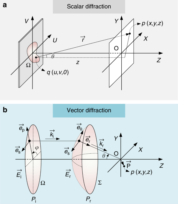
FOURIER TRANSFORM For scalar diffraction, as shown in Fig. 1a, the electric field at a point (_x, y, z_) in the Cartesian coordinates can be obtained based on the Huygens–Fresnel principle
and expressed by the Rayleigh–Sommerfeld diffraction integral20: $$E\left( {x,y,z} \right) = - \frac{i}{\lambda } {\iint_{\!\Omega}} {E_0\left( {u,v,0} \right) \times \frac{{\exp \left(
{ikr} \right)}}{r} \times \cos \theta \;} dudv$$ (1) where \(r = \sqrt {\left( {x - u} \right)^2 + \left( {y - v} \right)^2 + z^2}\) is the distance between the source point and the
observation point of interest. _k_ = 2_π_/_λ_ is the wavenumber. In the condition of the Fresnel approximation with a Fresnel number _F_ ≥ 1, the third term and higher orders in the Taylor
expression of _r_ can be ignored, that is, \(r \approx z + \frac{{\left( {x - u} \right)^2 + \left( {y - v} \right)^2}}{{2z}}\). In the denominator of Eq. (1), _r_ can be further
approximated with only the first term (_r_ ≈ _z_). Moreover, the paraxial approximation ensures cos_θ_ ≈ 1. In this way, the complex electric field can be described by the Fresnel
diffraction integral: $$E\left( {x,y,z} \right) = \frac{{\exp \left( {ikz} \right)}}{{i\lambda z}} {\iint_{\!\Omega}} {E_0\left( {u,v,0} \right) \times \exp \left\{ {\frac{{ik}}{{2z}}\left[
{\left( {x - u} \right)^2 + \left( {y - v} \right)^2} \right]} \right\}} dudv$$ (2) which can be further rewritten as: $$E\left( {x,y,z} \right) = \frac{{\exp \left( {ikz} \right) \times
\exp \left( {ik\frac{{x^2 + y^2}}{{2z}}} \right)}}{{i\lambda z}}{\iint}_{\!\Omega} {E_0\left( {u,v,0} \right) \times \exp \left[ {\frac{{i\pi }}{{\lambda z}}\left( {u^2 + v^2} \right)}
\right] \times {\mathrm{exp}}\left[ { - \frac{{2i\pi }}{{\lambda z}}\left( {xu + yv} \right)} \right]} dudv$$ (3) Here, we define: $$F_0 = \frac{{\exp \left( {ikz} \right) \times \exp \left(
{ik\frac{{x^2 + y^2}}{{2z}}} \right)}}{{i\lambda z}}$$ (4) $$F = \exp \left[ {\frac{{i\pi }}{{\lambda z}}\left( {u^2 + v^2} \right)} \right]$$ (5) Therefore, the integral Eq. (3) can be
expressed in terms of the two-dimensional FT: $$E = F_0 \times {\boldsymbol{F}}\left( {E_0 \times F} \right)$$ (6) here _F_ represents the two-dimensional FT. Moreover, as with the other
type of scalar diffraction, Fraunhofer diffraction in the far field can be expressed by \(E = F_0 \times {\boldsymbol{F}}\left( {E_0} \right)\), which can be regarded as a special case of
Fresnel diffraction passing through a converging lens. Therefore, scalar diffraction can be computed across the _xy_-plane using an FT-based approach. Scalar diffraction can be used to
effectively compute the complex amplitude distribution of many optical systems with a few approximations, as described above. However, it is known that the polarization components are
changed due to large refractivity after passing through a high-NA non-paraxial system, and scalar diffraction is incapable of achieving proper results. The vectorial Debye diffraction
integral, established by Richards and Wolf21, has to be adopted to analyze the complex EM field of each polarization component (Supplementary Information Section 1). The optical layout is
shown in Fig. 1b. Due to the refraction of the non-paraxial tight focusing system, the electric field components (polarization components \(\overrightarrow e _s\) and \(\overrightarrow e
_p\)) on the entrance pupil PE are transformed into a spherical reference surface PR (\(\overrightarrow e _s\), \(\overrightarrow e _{th}\), and \(\overrightarrow e _r\)). The transformation
can be expressed in Cartesian coordinates as20: $$\overrightarrow E _r = A_0\sqrt {\cos \theta } \times {\mathbf{M}} \,\times\, \overrightarrow E _i$$ (7) M is the transform matrix of the
polarization from the entrance surface to the converging spherical surface. \(A_0\sqrt {\cos \theta }\) is the apodization factor accounting for the energy conservation. The propagation of
the electric field from the reference surface PR to the imaging point _p_ (_x, y, z_) near the focus is expressed by the Debye integral: $$\overrightarrow E = - \frac{{iC}}{\lambda }\mathop
{\iint}\nolimits_{\!\Sigma} {\overrightarrow E _r} \times \exp \left[ {i\left( {k_zz - k_xx - k_yy} \right)} \right]{\mathrm{ }}d\Sigma$$ (8) The definition of \(\overrightarrow k _r\)can be
found in Supplementary Information Section 1. By performing the integration over the planar surface PE instead of the surface PR (Supplementary Information Section 2): $$\overrightarrow E =
- \frac{{iC}}{\lambda }\mathop {\iint}\nolimits_{\!\Omega} {\left[ {\overrightarrow E _r \times {{\exp \left( {ik_zz} \right)} / {\cos \theta }}} \right] \times \exp \left[ { - i\left(
{k_xx + k_yy} \right)} \right]} {\mathrm{ }}dk_xdk_y$$ (9) which can be rewritten in the form of an FT: $$\overrightarrow E \left( {x,y,z} \right) = - \frac{{iC}}{\lambda
}{\boldsymbol{F}}\left[ {\overrightarrow E _r \times {{\exp \left( {ik_zz} \right)} / {\cos \theta }}} \right] = - \frac{{iC}}{\lambda }{\boldsymbol{F}}\left[ {{\mathbf{M}} \times
\overrightarrow E _i \times {{\exp \left( {ik_zz} \right)} / {\sqrt {\cos \theta } }}} \right]$$ (10) In brief, both scalar diffraction and vector diffraction can be expressed by the FT. FFT
algorithms in modern computer systems allow for fast and accurate calculations. The similarity between these two diffractions is obvious from a mathematical point of view: the vector
diffraction integral is equivalent to the scalar Fraunhofer diffraction in the case of a low-NA optical system where 1/cos_θ_ ≈ 1. Although the FFT-based optical calculation is much faster
than the direct integration method, it results in inevitable drawbacks: the resultant output field has a fixed transverse dimension and unchangeable sampling numbers determined by the
dimension and sampling size of the input aperture for a given distance. The dimension of the output field is: $$D_m = \frac{{\lambda d}}{{p_s}}$$ (11) where _d_ is the distance between the
input aperture and output plane. _p__s_ is the sampling size of the input aperture. The sampling numbers of the output plane are rigidly equivalent to those of the input aperture. The
restriction is brought about by the intrinsic characteristic of the FT and greatly limits the flexibility in light propagation calculations. For example, the input aperture must be
enormously expanded with the aid of the zero-padding approach when a small portion of the output plane is required with high resolution, which inevitably leads to a large increment of the
computation time. BLUESTEIN METHOD TO COMPUTE FOURIER TRANSFORM WITH ARBITRARY ROI AND SAMPLING RESOLUTION Regarding mathematics, to achieve the required bandwidth and resolution in the
frequency domain, the appropriate zero-padding operation is needed to extend the dimension of the original input sequence15. For most applications in laser manipulation and lithography, only
a small fraction of the output field with high resolution is needed to obtain sufficient details, resulting in large amounts of zero-padding. This results in a severe waste of resources, as
most of the results are discarded. The operation of the zero-padding inevitably increases the computation time and the demand for memory usage. Moreover, the resultant output region remains
unchangeable, greatly limiting its potential in practical applications. Here, the Bluestein method is adopted to evaluate the scalar and vector diffraction calculations. The Bluestein
method is an elegant method conceived by L. Bluestein22 and further generalized by L. Rabiner et al.23 that is capable of performing more general FTs at arbitrary frequencies as well as
boosting the resolution over the full spectrum. The Bluestein method offers us a spectral zoom operation with high resolution and arbitrary bandwidth. This advantage is enabled by computing
the z-transform along spiral contours in the _z_-plane for an input sequence (Supplementary Information Section 3 and Fig. S1). The computational complexity is _O_[(_M_ + _N_)log2(_M_ +
_N_)], manifesting an FFT algorithm. The method is based on the z-transform along a spiral contour in the _z_-plane defined by _A_ and _W_: $$X\left[ m \right] = \left. {\mathop
{\sum}\limits_{n = 0}^{N - 1} {x\left[ n \right] \times z^{ - n}} } \right|_{z = A \times W^{ - m}} = \mathop {\sum}\limits_{n = 0}^{N - 1} {x\left[ n \right] \times A^{ - n} \times
W^{mn}}$$ (12) here \(m = \left[ {0, \cdots ,M - 1} \right]\). _M_ is the length of the transform. _N_ is the length of input sequence. _A_ specifies the complex starting point of the
_z_-plane spiral contour of interest, and _W_ specifies the complex scalar describing the complex ratio between points along the contour. Note that the case of _A_ = 1, _W_ =
exp(−_i_2_π/N_), and _M_ = _N_ corresponds to the discrete Fourier transform (DFT), which computes the z-transform along the unit circle with a finite duration. More generally, the method
can be used to calculate the DFT between an arbitrary starting point _f__1_ and ending point _f__2_ (i.e., the tuneable frequency bandwidth relative to the total frequency range _f__s_) with
arbitrary sampling numbers _M_. The practical implementations of the Bluestein method for enhanced DFT computation deserve additional comments. First, a 2D FT is needed for the computation
of both scalar and vector diffraction. The Bluestein method should be adopted in both the column and the row dimensions to fulfill this requirement. Second, the Bluestein method internalizes
padding of the input array with zeros at the tail. However, symmetric zero-padding around the input array is needed for the simulation of realistic optical systems. Third, an additional
operation is needed to shift the zero-frequency component to the center of the array before and after the DFT to eliminate the high-frequency oscillation in the phase information. To address
these issues, the definition of parameters _A_ and _W_ should be rearranged, and phase shifting factor _P_shift should be included at the end of the calculation (see Supplementary
Information Section 3 and Figs. S2–S4). By performing these adjustments, the Bluestein method can be developed as a fast approach for light diffraction calculation with superior flexibility:
it allows for the selection of arbitrary segments in the imaging plane with arbitrary resolution, providing competitive efficiency and flexibility over direct integration and the FFT
methods. FAST NUMERICAL IMPLEMENTATION OF THE BLUESTEIN METHOD IN SCALAR FRESNEL DIFFRACTION Figure 2 illustrates the scalar calculation with a paradigm of the converging spherical wave
propagation, which is generated by a plane wave passing through a convex lens. The phase profile of the lens is shown in Fig. 2a, which is equivalent to the phase plate after being wrapped
between 0 and 2_π_ (Fig. 2b). The optical configuration is sketched in Fig. 2c, with the parameters _λ_ = 800 nm, _f_ = 600 mm, and _D_ = 8.64 mm. Figure 2d, e shows the optical field
distribution in the focal plane in terms of the intensity and phase. Figure 2f, g shows the cross-sectional intensity and phase distributions in the light propagation direction. The
corresponding line plots of the intensity and phase are given in Fig. 2h–k. A comparison between the Bluestein method and traditional direct integration and FFT methods is also made, from
which we can see excellent agreements. It is revealed that the Bluestein method can calculate the scalar light diffraction with high accuracy. The Bluestein method has a superior advantage
in the computation time cost over the direct integration and FFT methods. Due to the tedious point-by-point calculation method, the direct integration method is associated with two cycling
loops, and the computation time increases drastically with the calculation points of the target plane (with a computational complexity of _O_ (_M__2_ × _N__2_)). For the case of the FFT
method, a zero-padding operation is needed to fulfill the requirement for the pre-set target sampling numbers, resulting in a rapid increase in computation time with the sampling points. As
shown in Fig. 2l, with the increase in the sampling points along one coordinate axis, the Bluestein method exhibits its obvious superiority compared with the other two methods. This
advantage makes the method particularly applicable to scenarios where large sampling points are needed, such as high-resolution microscopy. For the case in Fig. 2d, e, where the sampling
points in the entrance pupil and output field are the same (_M_ = _N_ = 1080) and the ROI is 0.2 × 0.2 mm, the computational cost is ~13.7 h for the direct integration method, making it
unsuitable for practical applications. For the FFT method, the computational cost is improved to 68 s, as shown in Fig. 2m. In comparison, the computation time is only 0.67 s using our
proposed Bluestein method, which is 105 and 102 times less than those of the direct integration method and FFT method, respectively. The three-dimensional volumetric light field
(Supplementary Information Fig. S5) can be reconstructed using cross-sectional light fields by calculating the lateral planes layer by layer. As depicted in Fig. 2n, the computation time for
the direct method is excessively long to obtain the volumetric light field (~85 days). It takes 2 h to calculate the cross-sectional light field in the longitudinal _yz_-plane. By using the
FFT method, the computational cost is the same (2.8 h) for both the volumetric and cross-sectional light fields because the ROI cannot be tuned due to the intrinsic characteristic of the
FT. Owing to the fast computation property of the Bluestein method, calculation of the 3D optical field can be accomplished in <100 s. The efficiency enhancement is on the same order as
that in the lateral _xy_-plane. More examples of scalar diffraction are given in Supplementary Information Section 4 and Fig. S6. In addition to the great improvement in computational
efficiency, the Bluestein method has remarkable flexibility compared with the FFT method. That is, an arbitrary ROI can be defined with arbitrary resolution. This feature is illustrated by
reconstructing a computer-generated hologram (CGH), as shown in Fig. 3. Evaluation of the light propagation after being modulated by a CGH is essential for predicting the performance of
optical holographic tweezers24, holographic displays25, and laser holographic processing26,27. As shown in Fig. 3a, a CGH is generated by the weighted Gerchberg–Saxton (GSW) algorithm28,29.
After FT by a converging FT lens, the designed pattern can be reconstructed (Fig. 3b). The process involves two scalar diffraction calculations: one is from the CGH to the FT lens, and the
other is from the FT lens to the reconstruction plane. Figure 3c–f shows the intensity distributions with varying regions in the reconstruction plane and constant sampling points (1080 ×
1080). Figure 3g–j shows the corresponding phase distributions. It is validated that the Bluestein method possesses fine flexibility compared with the FFT method. FAST NUMERICAL CALCULATION
OF THE VECTORIAL DEBYE DIFFRACTION The vectorial nature of light is essential for optical systems with a high-NA aperture or specific polarization, such as radial and azimuthal
polarizations30,31. Figure 4a illustrates the focusing of radially polarized light by a high-NA aplanatic objective (NA: 1.4). By using the proposed Bluestein method in the vectorial
Debye–Wolf integral, the light field distribution near the focus can be rapidly calculated (insets of Fig. 4a). The results are consistent with those computed by direct integration and the
FFT methods, as reflected by the line plots of the light intensity along the transverse and longitudinal directions in Fig. 4b, c. The optical vortex generated by a spiral phase plate (Fig.
4d), in cooperation with circular polarization, plays a key role in super-resolution stimulated emission depletion microscopy32 and nano-lithography33. A doughnut-shaped focus profile with a
dark center is used as the depletion beam to eliminate fluorescence or polymerization. Figure 4e, j shows the optical intensity profiles of the optical vortex in the lateral _xy_ and
longitudinal _yz_-planes, respectively. An engineered focus with a symmetric doughnut shape can be generated. Moreover, the light components in different polarizations can be obtained
efficiently using our Bluestein method, as shown in Fig. 4f–i, k–m. It can be seen that all the light components have dark central intensities close to zero and the spiral phase. The light
in the transverse polarizations is dominant over the longitudinal polarization. The Bluestein method also endows the vectorial calculation with high flexibility compared with the traditional
FFT approach. Figure 4n, o shows the enlarged intensity profiles in the ROIs labeled in Fig. 4f, g, respectively. Another example of the usage of the Bluestein method for vector diffraction
is shown in Supplementary Information Section 5 and Fig. S7. The optical information in the arbitrary ROIs can be investigated in detail without increasing the computational cost, making
the Bluestein method advantageous in evaluating localized high-resolution light distributions for the application of microscopy and photolithography. For the computation time, the Bluestein
method also exhibits great superiority. Here, we consider the calculation from the entrance pupil with ~105 sampling points to the exit pupil with the same points in the _xy_-plane, and 100
layers along the optical axis are calculated for volumetric and cross-sectional light distributions in the _yz_-plane. As shown in Fig. 4p, the direct method requires 57.16 min to calculate
the lateral light field. 95.3 h is needed for the volumetric 3D light field distribution, and 22.78 min is needed for the sliced _yz_-plane. An acceptable time (2.88 s) is needed for the FFT
method to calculate the _xy_-plane. However, an impractical 280.4 s is needed to obtain the light distribution in the volumetric three dimensions and the two-dimensional _yz_-plane. In
contrast, only 0.2 s is consumed by the Bluestein method for calculation in the _xy_-plane. Moreover, only 9.34 and 12.19 s is needed to achieve the 2D cross-sectional and 3D volumetric
light fields. Note that the computation time increases much more quickly with the sampling numbers of the ROI for the direct method and FFT method than for the Bluestein method, e.g., more
than 10 days are needed for the direct method and 126.5 s is needed for the FFT method to acquire transverse light distributions in the _xy_-plane when the number of sampling points
increases to ~106 (1080 × 1080), while only 1.78 s is needed for the Bluestein method, which is five orders of magnitude less than that needed for the direct method and 102 times less than
that for the FFT method. FULL-PATH OPTICAL CALCULATION WITH SUPERIOR FLEXIBILITY AND EFFICIENCY As discussed above, both the scalar and vector diffraction can be efficiently calculated by
the Bluestein method. Based on this, the full-path optical calculation and tracing can be performed with high flexibility and efficiency. Figure 5a illustrates a representative optical
layout for laser holographic processing and holographic manipulation. This setup can be further adopted for two-photon scanning confocal microscopy. Here, a phase-only spatial light
modulator (SLM, Holoeye Pluto NIR-II, resolution: 1920 × 1080) is used to modulate the wavefront of the laser by loading a predesigned CGH. A combination of a half-wave plate and
polarization beam splitter is utilized to attenuate the laser power. A 4_f_ configuration consisting of Lens 1 (_f_ = 600 mm) and Lens 2 (_f_ = 200 mm) is placed between the SLM and
aplanatic objective (100×, NA: 1.4). It is a typical optical system involving both scalar diffraction and vector diffraction during light propagation. First, we simulate the multi-foci
optical system, which can be used for holographic tweezers, laser parallel processing and data recording. Figure 5b is the corresponding CGH for the generation of a 9 × 9 multi-foci array. A
linearly polarized femtosecond laser (800 nm, emitted from Chameleon Vision-S, Coherent) is modulated by the CGH. After the FT of Lens 1, a multi-foci array is generated (Fig. 5c). At the
back of the objective, the phase and intensity distributions are retrieved as shown in Fig. 5d, e. The phase profile closely resembles the CGH, validating the accuracy of the
Bluestein-enabled calculation of scalar diffraction. The light beam is slightly smaller than the size of the entrance pupil of the objective, ensuring that the phase-modulated beam can be
fully transformed by the objective. In the focal plane of the objective, a diffraction-limited 9 × 9 multi-foci array is generated (Fig. 5f). The full-path calculation can be accomplished
with high efficiency in <4 s. The experimentally measured multi-foci intensity (Fig. 5g) agrees well with the simulation. With the help of the highly flexible Bluestein method, a detailed
analysis of a single focal spot is enabled, as shown in Fig. 5h, revealing that a Gaussian focus is generated with linear polarization. The light field in the longitudinal section can be
readily computed, and the spatial uniformity can be investigated (Fig. 5i). Another universal example is given in Fig. 5j–m, where a CGH is encoded on the SLM to generate a pattern as
discussed in Fig. 3. By using the Bluestein full-path calculation method, the light field of the desired pattern can be simulated in the focal plane of the objective (Fig. 5j), consistent
with the experimental result (Fig. 5k). By taking advantage of the high flexibility of the Bluestein method, a magnified image of an arbitrary ROI can be calculated with arbitrary resolution
and good accuracy in comparison with the experimental result, as shown in Fig. 5l, k. Another example of the usage of the Bluestein method for vector diffraction is shown in Supplementary
Information Section 6 and Fig. S8. In brief, full-path light tracing of the entire optical system can be accomplished by the Bluestein method with high efficiency and flexibility, unfolding
its capacities in the real-time prediction and evaluation of optical performance in advanced microscopy, laser manipulation, and photolithography. DISCUSSION The proposed Bluestein-based
method provides a fundamental improvement in optical diffraction calculations. The advantages of the method lie in the following three aspects. First, the computation method for light
diffraction is superfast, allowing for the real-time prediction of light field propagation for diverse implementations. Second, the method has great flexibility, without loss of accuracy and
efficiency. The desired ROI can be freely chosen, and the sampling numbers can be arbitrarily tuned. Third, the method shows good universality. It suits all diffraction conditions, such as
phase modulation, amplitude filtering, polarization conversion, and focusing transform. In particular, this method facilitates the simulation and optimal design of metasurfaces34,35,36, as
exemplified in Supplementary Information Section 7 and Fig. S9. Both scalar and vector diffraction can be computed using this method, making this method promising for full-path propagation
evaluation in broad applications of optical microscopy, lithography, and optical manipulation. In addition, the applicability of this method needs to be explicated for realistic
implementations. First, some approximation conditions are assumed for both vector and scalar diffraction. For vector diffraction, the lens is assumed to obey Abbe’s sine condition. For
scalar diffraction, the Fresnel approximation should be valid. It is worth noting that Fraunhofer diffraction can also be implemented using the Bluestein method with slight modification.
Second, it is important to take stringent precautions against aliasing effects. When the diffraction distance of scalar diffraction is too small or the focal shift of vector diffraction is
too long, obvious aliasing is likely to occur because the sampling condition no longer satisfies the Nyquist sampling condition. In summary, an efficient calculation method is developed to
evaluate light diffraction with high flexibility and efficiency. First, a set of mathematical preliminaries is given to express the scalar and vector diffraction integrals in the form of an
FT and then unified using the Bluestein method. Examples for both scalar and vector diffraction are demonstrated to reveal that the computational efficiency and flexibility are greatly
improved. Calculation of the light field is realized at the sub-second time level compared with several minutes using the FFT method or hours using the direct integration method. Full-path
light tracing is finally demonstrated using the Bluestein method. This method holds great potential not only in the fast prediction of numerous optical systems but also in the realm of
signal processing for acoustic and other communication waves. MATERIALS AND METHODS COMPUTATIONAL ENVIRONMENT All the calculations are performed on a personal laptop with an Intel processor
I5 2.50 GHz and 8 GB of memory, running the Windows 10 Professional operating system. The code is written, compiled and run in the MATLAB R2019a software. All the comparison studies on
efficiency are performed in the same computational environment. LASER HOLOGRAPHIC SYSTEM The laser holographic system consists of a Ti:sapphire femtosecond laser oscillator (Chameleon
Vision-S, Coherent) with a central wavelength of 800 nm, a repetition rate of 80 MHz, and a pulse width of 75 fs. A phase-only reflective liquid crystal SLM (Pluto NIR-2, Holoeye) is
utilized for the phase modulation, which features a 1920 × 1080 resolution and a 8 μm pixel pitch. In the experiment, only the central portion of the SLM with 1080 × 1080 pixels is used to
modulate the wavefront, while the other pixels are set to zero. A phase hologram pattern with 256 different shades of gray is loaded onto the SLM, corresponding to the phase modulation depth
from 0 to 2_π_. A CCD camera is used to capture the light field distribution. REFERENCES * Willig, K. I., Harke, B., Medda, R. & Hell, S. W. STED microscopy with continuous wave beams.
_Nat. Methods_ 4, 915–918 (2007). Article Google Scholar * Kawata, S. et al. Finer features for functional microdevices. _Nature_ 412, 697–698 (2001). Article ADS Google Scholar *
Andrew, T. L., Tsai, H. Y. & Menon, R. Confining light to deep subwavelength dimensions to enable optical nanopatterning. _Science_ 324, 917–921 (2009). Article ADS Google Scholar *
Scott, T. F. et al. Two-color single-photon photoinitiation and photoinhibition for subdiffraction photolithography. _Science_ 324, 913–917 (2009). Article ADS Google Scholar * Li, L. J.
et al. Achieving λ/20 resolution by one-color initiation and deactivation of polymerization. _Science_ 324, 910–913 (2009). Article ADS Google Scholar * Grier, D. G. A revolution in
optical manipulation. _Nature_ 424, 810–816 (2003). Article ADS Google Scholar * Block, S. M. Making light work with optical tweezers. _Nature_ 360, 493–495 (1992). Article ADS Google
Scholar * Mezouari, S. & Harvey, A. R. Validity of fresnel and fraunhofer approximations in scalar diffraction. _J. Opt. A_ 5, S86–S91 (2003). Article ADS Google Scholar * Sheppard,
C. J. R. & Matthews, H. J. Imaging in high-aperture optical systems. _J. Opt. Soc. Am. A_ 4, 1354–1360 (1987). Article ADS Google Scholar * Lee, K. G. et al. Vector field microscopic
imaging of light. _Nat. Photonics_ 1, 53–56 (2007). Article ADS Google Scholar * Dorn, R., Quabis, S. & Leuchs, G. Sharper focus for a radially polarized light beam. _Phys. Rev.
Lett._ 91, 233901 (2003). Article ADS Google Scholar * Wolf, E. Electromagnetic diffraction in optical systems. I. An integral representation of the image field. _Proc. R. Soc. A_ 253,
349–357 (1959). ADS MathSciNet MATH Google Scholar * Hao, X., Kuang, C. F., Wang, T. T. & Liu, X. Effects of polarization on the de-excitation dark focal spot in STED microscopy. _J.
Opt._ 12, 115707 (2010). Article ADS Google Scholar * Urbach, H. P. & Pereira, S. F. Field in focus with a maximum longitudinal electric component. _Phys. Rev. Lett._ 100, 123904
(2008). Article ADS Google Scholar * Leutenegger, M. et al. Fast focus field calculations. _Opt. Express_ 14, 11277–11291 (2006). Article ADS Google Scholar * Lin, J. et al. Fast
vectorial calculation of the volumetric focused field distribution by using a three-dimensional Fourier transform. _Opt. Express_ 20, 1060–1069 (2012). Article ADS Google Scholar * Lin,
J. et al. Direct calculation of a three-dimensional diffracted field. _Opt. Letters_ 36, 1341–1343 (2011). Article ADS Google Scholar * Boruah, B. R. & Neil, M. A. A. Focal field
computation of an arbitrarily polarized beam using fast Fourier transforms. _Opt. Commun._ 282, 4660–4667 (2009). Article ADS Google Scholar * Nie, Z. Q. et al. Three-dimensional
super-resolution longitudinal magnetization spot arrays. _Light Sci. Appl._ 6, e17032 (2017). Article Google Scholar * Born, M. & Wolf, E. _Principles of Optics_ 7th edn (Cambridge
University Press, Cambridge, 1999). * Richards, B. & Wolf, E. Electromagnetic diffraction in optical systems, II. Structure of the image field in an aplanatic system. _Proc. R. Soc. A_
253, 358–379 (1959). ADS MATH Google Scholar * Bluestein, L. A linear filtering approach to the computation of discrete Fourier transform. _IEEE Trans. Audio Electroacoust._ 18, 451–455
(1970). Article Google Scholar * Rabiner, L., Schafer, R. & Rader, C. The chirp z-transform algorithm. _IEEE Trans. Audio Electroacoust._ 17, 86–92 (1969). Article Google Scholar *
Kim, H. et al. In situ single-atom array synthesis using dynamic holographic optical tweezers. _Nat. Commun._ 7, 13317 (2016). Article ADS Google Scholar * Li, X. P. et al. Athermally
photoreduced graphene oxides for three-dimensional holographic images. _Nat. Commun._ 6, 6984 (2015). Article ADS Google Scholar * Hu, Y. L. et al. High-efficiency fabrication of aspheric
microlens arrays by holographic femtosecond laser-induced photopolymerization. _Appl. Phys. Lett._ 103, 141112 (2013). Article ADS Google Scholar * Ni, J. C. et al. Three-dimensional
chiral microstructures fabricated by structured optical vortices in isotropic material. _Light Sci. Appl._ 6, e17011 (2017). Article Google Scholar * Zalevsky, Z., Mendlovic, D. &
Dorsch, R. G. Gerchberg–Saxton algorithm applied in the fractional Fourier or the Fresnel domain. _Opt. Lett._ 21, 842–844 (1996). Article ADS Google Scholar * Hu, Y. L. et al. Fast bits
recording in photoisomeric polymers by phase-modulated femtosecond laser. _IEEE Photonics Technol. Lett._ 26, 1154–1156 (2014). Article ADS Google Scholar * Wang, H. F. et al. Creation of
a needle of longitudinally polarized light in vacuum using binary optics. _Nat. Photonics_ 2, 501–505 (2008). Article Google Scholar * Wang, S. C. et al. Ultralong pure longitudinal
magnetization needle induced by annular vortex binary optics. _Opt. Lett._ 39, 5022–5025 (2014). Article ADS Google Scholar * Hell, S. W. & Wichmann, J. Breaking the diffraction
resolution limit by stimulated emission: stimulated-emission-depletion fluorescence microscopy. _Opt. Lett._ 19, 780–782 (1994). Article ADS Google Scholar * Gan, Z. S. et al.
Three-dimensional deep sub-diffraction optical beam lithography with 9 nm feature size. _Nat. Commun._ 4, 2061 (2013). Article ADS Google Scholar * Yu, N. F. et al. Light propagation with
phase discontinuities: generalized laws of reflection and refraction. _Science_ 334, 333–337 (2011). Article ADS Google Scholar * Khorasaninejad, M. et al. Metalenses at visible
wavelengths: diffraction-limited focusing and subwavelength resolution imaging. _Science_ 352, 1190–1194 (2016). Article ADS Google Scholar * Yu, N. F. & Capasso, F. Flat optics with
designer metasurfaces. _Nat. Mater._ 13, 139–150 (2014). Article ADS Google Scholar Download references ACKNOWLEDGEMENTS This work was supported by the National Natural Science Foundation
of China (Nos. 51875544, 91963127, 51675503, 61805230, 51805509), USTC Research Funds of the Double First-Class Initiative (Grant No. YD2090002005), Youth Innovation Promotion Association
of the Chinese Academy of Sciences (2017495), and National Key R&D Program of China (2018YFB1105400). The USTC Center for Micro and Nanoscale Research and Fabrication is also
acknowledged. AUTHOR INFORMATION AUTHORS AND AFFILIATIONS * CAS Key Laboratory of Mechanical Behavior and Design of Materials, Key Laboratory of Precision Scientific Instrumentation of Anhui
Higher Education Institutes, Department of Precision Machinery and Precision Instrumentation, University of Science and Technology of China, Hefei, 230026, China Yanlei Hu, Zhongyu Wang,
Shengyun Ji, Jiawen Li, Wulin Zhu, Dong Wu & Jiaru Chu * Department of Mechanical Engineering and Department of Civil and Environmental Engineering, Massachusetts Institute of
Technology, Cambridge, MA, 02139, USA Yanlei Hu * State Key Laboratory of Advanced Technology for Materials Synthesis and Processing, International School of Materials Science and
Engineering, Wuhan University of Technology, Wuhan, 430070, China Xuewen Wang * Institute of Industry and Equipment Technology, Hefei University of Technology, Hefei, 230009, China Chenchu
Zhang Authors * Yanlei Hu View author publications You can also search for this author inPubMed Google Scholar * Zhongyu Wang View author publications You can also search for this author
inPubMed Google Scholar * Xuewen Wang View author publications You can also search for this author inPubMed Google Scholar * Shengyun Ji View author publications You can also search for this
author inPubMed Google Scholar * Chenchu Zhang View author publications You can also search for this author inPubMed Google Scholar * Jiawen Li View author publications You can also search
for this author inPubMed Google Scholar * Wulin Zhu View author publications You can also search for this author inPubMed Google Scholar * Dong Wu View author publications You can also
search for this author inPubMed Google Scholar * Jiaru Chu View author publications You can also search for this author inPubMed Google Scholar CONTRIBUTIONS Y.H. conceived the idea and
developed the theory. Y.H., Z.W., and X.W. performed the simulations. S.J., C.Z. W.Z., and D.W. performed the experimental measurements. Y.H., X.W., J.L., D.W., and J.C. analyzed the data.
Y.H., C.Z., J.L., D.W., and J.C. wrote the paper. J.L. and D.W. supervised the project. All authors discussed the results and commented on the paper. CORRESPONDING AUTHORS Correspondence to
Jiawen Li or Dong Wu. ETHICS DECLARATIONS CONFLICT OF INTEREST The authors declare that they have no conflict of interest. SUPPLEMENTARY INFORMATION SUPPLEMENTARY INFORMATION RIGHTS AND
PERMISSIONS OPEN ACCESS This article is licensed under a Creative Commons Attribution 4.0 International License, which permits use, sharing, adaptation, distribution and reproduction in any
medium or format, as long as you give appropriate credit to the original author(s) and the source, provide a link to the Creative Commons license, and indicate if changes were made. The
images or other third party material in this article are included in the article’s Creative Commons license, unless indicated otherwise in a credit line to the material. If material is not
included in the article’s Creative Commons license and your intended use is not permitted by statutory regulation or exceeds the permitted use, you will need to obtain permission directly
from the copyright holder. To view a copy of this license, visit http://creativecommons.org/licenses/by/4.0/. Reprints and permissions ABOUT THIS ARTICLE CITE THIS ARTICLE Hu, Y., Wang, Z.,
Wang, X. _et al._ Efficient full-path optical calculation of scalar and vector diffraction using the Bluestein method. _Light Sci Appl_ 9, 119 (2020).
https://doi.org/10.1038/s41377-020-00362-z Download citation * Received: 12 May 2020 * Revised: 23 June 2020 * Accepted: 28 June 2020 * Published: 13 July 2020 * DOI:
https://doi.org/10.1038/s41377-020-00362-z SHARE THIS ARTICLE Anyone you share the following link with will be able to read this content: Get shareable link Sorry, a shareable link is not
currently available for this article. Copy to clipboard Provided by the Springer Nature SharedIt content-sharing initiative